Ear plug to be inserted into the external auditory canal

a technology for external auditory canals and ear plugs, which is applied in the field of ear plugs, can solve the problems of clogging of the ear, remarkably reducing the performance of the ear plugs, and affecting the sound quality of the ear, so as to prevent sound leakage and reduce the pressure difference

Inactive Publication Date: 2004-07-13
MIMY ELECTRONICS
View PDF2 Cites 11 Cited by
  • Summary
  • Abstract
  • Description
  • Claims
  • Application Information

AI Technical Summary

Benefits of technology

Consequently, an object of the present invention is to lengthen a communicating passage or vent to an effective degree for remarkably decreasing the pressure difference between the inside of the external auditory canal and the external atmosphere as well as preventing leakage of sound causing so-called howling.

Problems solved by technology

However, if the degree of prevention of noise is improved at that time, there occurs a pressure difference between the external atmosphere and an inside of the external auditory canal, accompanied by problems such as feeling of oppression with clogging of the ear.
This causes so-called howling to remarkably decrease the performance of the ear plug.

Method used


Image

  • Ear plug to be inserted into the external auditory canal
  • Ear plug to be inserted into the external auditory canal
  • Ear plug to be inserted into the external auditory canal

Examples


second embodiment

The positions of the vents 6 and 7 serve to effectively lengthen the communicating passage. These vents can be formed as notched portions 8 and 9 at different positions of respective projections 5, particularly at-an angular interval of 180.degree. according to the present invention as shown in FIGS. 5 and 6. The outermost vent 3 can be easily formed when it is groove-shaped instead of the penetrating hole of FIG. 2.

third embodiment

FIG. 7 shows a core member of an ear plug wherein a continuous vent or groove 11 is formed along a continuously formed spiral-shaped projection or ridge 10 like a single projection to make the outermost vent 3 communicate with the external auditory canal.

Also in this construction of the ear plug of FIG. 7 having the core member 21 with the spiral-shaped projection 10 and the sleeve member 2 as already shown in FIG. 2, the continuous vent 11 extending along the projection 10 serves to make the external auditory canal 13 communicate with the external atmosphere so as to lengthen a communicating passage or vent to an effective degree for remarkably decreasing only the pressure difference between the inside of the external auditory canal 13 and the external atmosphere as well as preventing leakage of sound causing so-called howling. Besides, the spiral-shaped projection 10 can be easily formed on the core member 21 like an external thread.

embodiment 25

FIG. 8 shows a further embodiment 25 of an ear plug with a hearing aid 12 having the sleeve member 2 attached to the core member 21 as shown in FIG. 7.

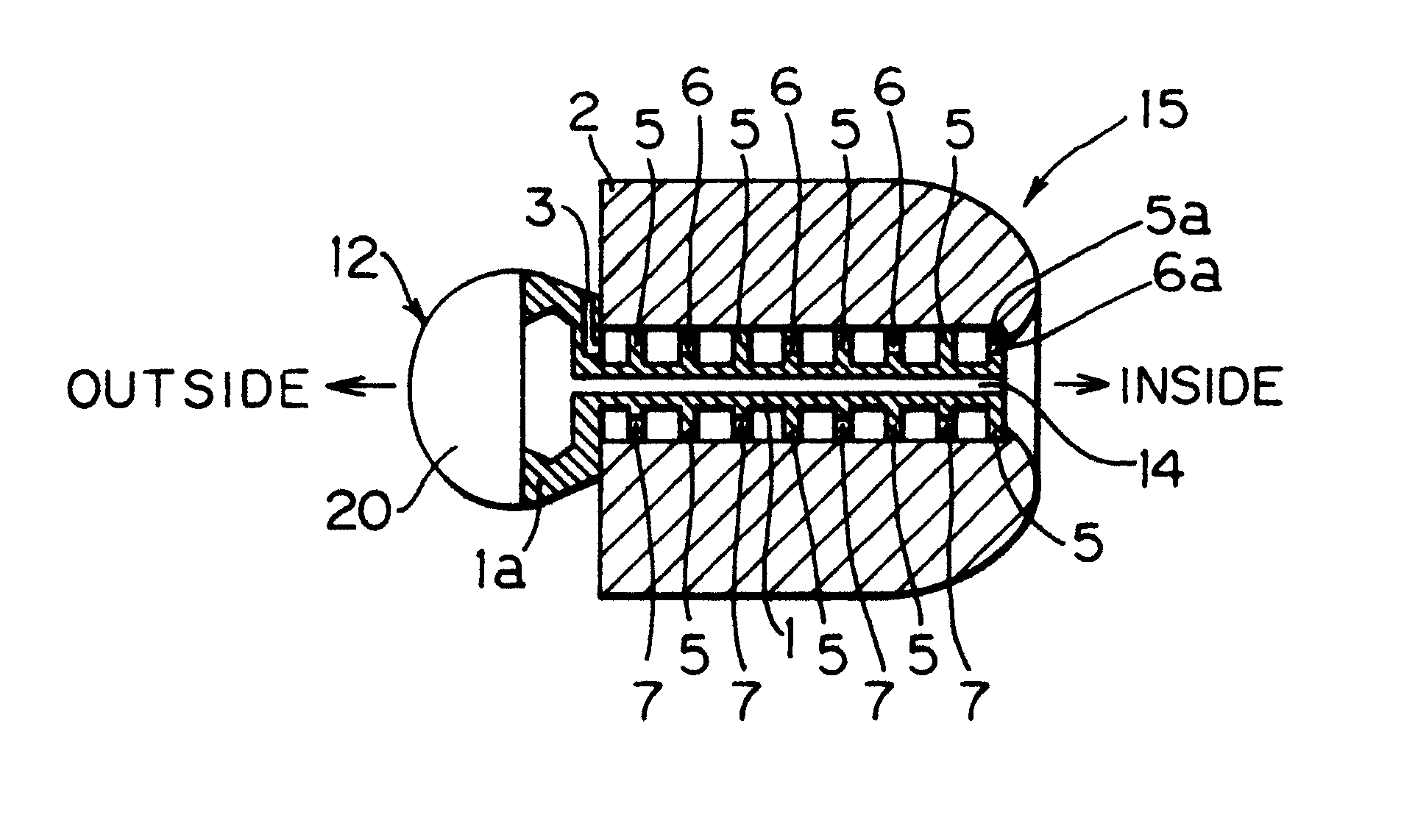
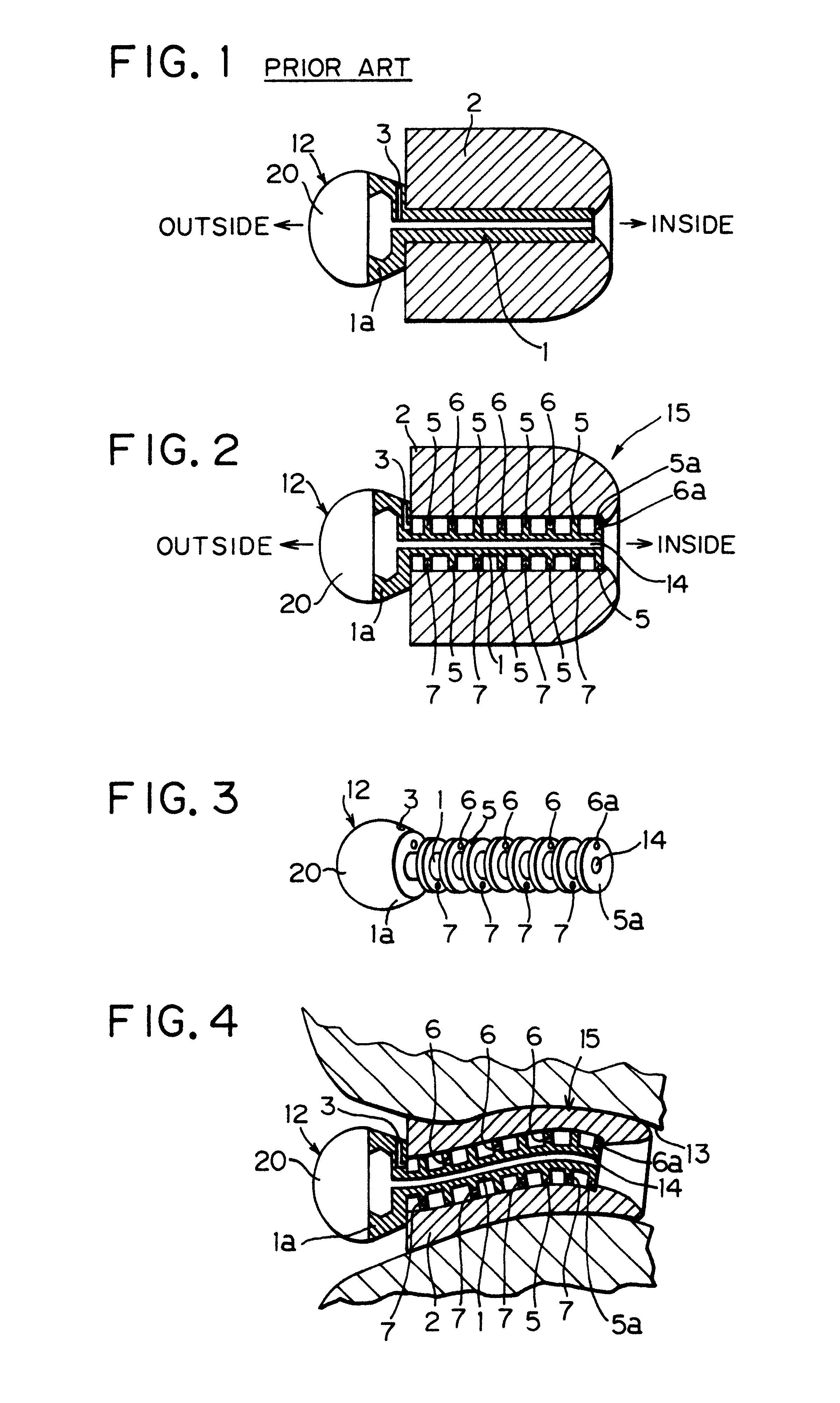
The above-described ear plug 15 or 25 comprises the hearing aid 12 having a sound amplifier portion 20 and a sound guide portion 1 or 21 which functions also as a core member, the plural projections 5 or the spiral-shaped projection 10 formed on the exterior of the sound guide portion 1 or 21 wherein the vent 6 or 11 is defined in respective projections 5 or 10 and the outermost vent 3 is defined in the enlarged portion 1a or 21a of the core member, and the compressible sleeve member 2 adhered to the circumference of the projection 5 or 10.

The ear plug 25 can be easily manufactured as well as the ear plug 15 because the core member is a part of the hearing aid 12 and so it is not necessary to attach a separate hearing aid to the core member. Moreover, the afore said embodiments shown in FIG. 2 to FIG. 7 can be variously modified, for ...


PUM


Abstract

An ear plug to be inserted into the external auditory canal, having a compressible sleeve member and a core member attached therein, the improvement in which plural projections or a single projection are formed intermittently or continuously on an exterior of the core member, and vent is formed through or along the projection to make the external auditory canal communicate with the external atmosphere when inserted into the external auditory canal. A communicating passage or vent to an effective degree for remarkably decreasing the pressure difference between the inside of the external auditory canal and the external atmosphere as well as preventing leakage of sound causing so-called howling.

Description

INDUSTRIAL FIELD OF THE INVENTIONThe present invention relates to an ear plug usable for prevention of noise, acoustic instruments such as hearing aids, and so on.PRIOR ARTFIG. 1 shows the prior art ear plug wherein a sponge-like sleeve member 2 is fixed on an exterior of a core member 1 in a body. An external enlarged portion la of the core member 1 has a shallow vent 3 formed therethrough to loose a pressure difference between an interior of the external auditory canal and the external atmosphere when the ear plug is inserted into the external auditory canal. The core member 1 is formed as a part of a hearing aid 12.It is required that the ear plug is superior in prevention of noise of high frequency when inserted into the external auditory canal. However, if the degree of prevention of noise is improved at that time, there occurs a pressure difference between the external atmosphere and an inside of the external auditory canal, accompanied by problems such as feeling of oppressio...

Claims


Application Information

Patent Timeline
Patent Type & Authority Patents(United States)
IPC IPC(8): A61F11/08A61F11/00
CPCA61F11/08A61F2011/085A61F11/085
Inventor KUNO, TAKASHIOWADA, KENJIROOHGUSHI, MASAHIKO
Owner MIMY ELECTRONICS
Why Eureka
Try Eureka