
Optical module

a technology of optical transceivers and optical modules, applied in semiconductor lasers, circuit-breaking switches, instruments, etc., can solve the problems of deteriorating sensitivity of such optical transceivers, affecting the operation of optical transceivers, and external noise,

Inactive Publication Date: 2004-06-29
SUMITOMO ELECTRIC IND LTD
View PDF4 Cites 4 Cited by
  • Summary
  • Abstract
  • Description
  • Claims
  • Application Information

AI Technical Summary

Benefits of technology

This configuration effectively suppresses mutual interference and external noise, enhancing the optical transceiver's characteristics and stability, as demonstrated by improved EMI and RES test results and resistance to connector attaching / detaching operations.

Problems solved by technology

In the SFF or SFP optical transceiver, due to its small size, its optical transmitter unit and optical receiver unit are located close to each other, whereby they are likely to interfere with each other when dealing with digital signals having such a high frequency.
Also, they are susceptible to external noise, whereby the sensitivity of such an optical transceiver is more likely to be deteriorated by crosstalk as compared with optical transceivers having a large size.
If the angle is greater than 80.degree., it will be unfavorable since the pressing effect caused by the sliding becomes insufficient.

Method used


Image

  • Optical module
  • Optical module
  • Optical module

Examples


Embodiment Construction

equipped with the light-receiving device bracket 6 alone, and Example 2 equipped with the light-emitting device bracket 7 alone. It was seen that the noise suppressing effect attained by placing a bracket was greater in a higher frequency region.

FIGS. 13 and 14 are graphs showing results of RES characteristic tests on the reception side concerning Example 3 equipped with both of the brackets 6, 7 and the above-mentioned Examples 1, 2 and Comparative Example. As shown in the graph, the effect of improving RES characteristics was seen when placing a bracket on the reception side in particular.

FIGS. 15A and 15B are charts comparing the transmission waveform (FIG. 15A) in Example 3 and the transmission waveform (FIG. 15B) in Comparative Example. It was seen that Example 3 yielded a transmission waveform more stable than that in Comparative Example due to the designing of brackets and wiring patterns, thereby suppressing the crosstalk amount to 0.38 dB from 0.92 dB of Comparative Example...


PUM


Abstract

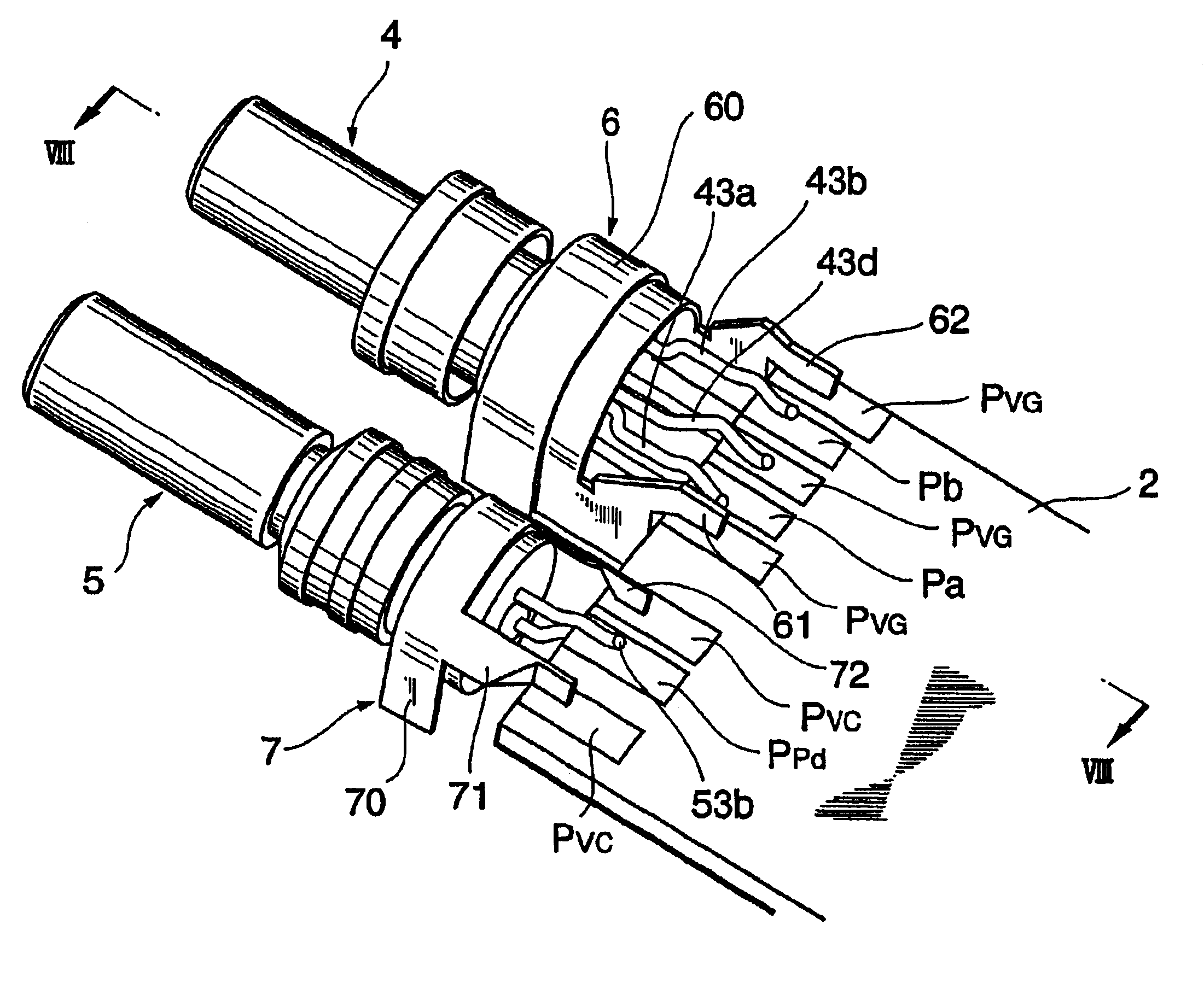
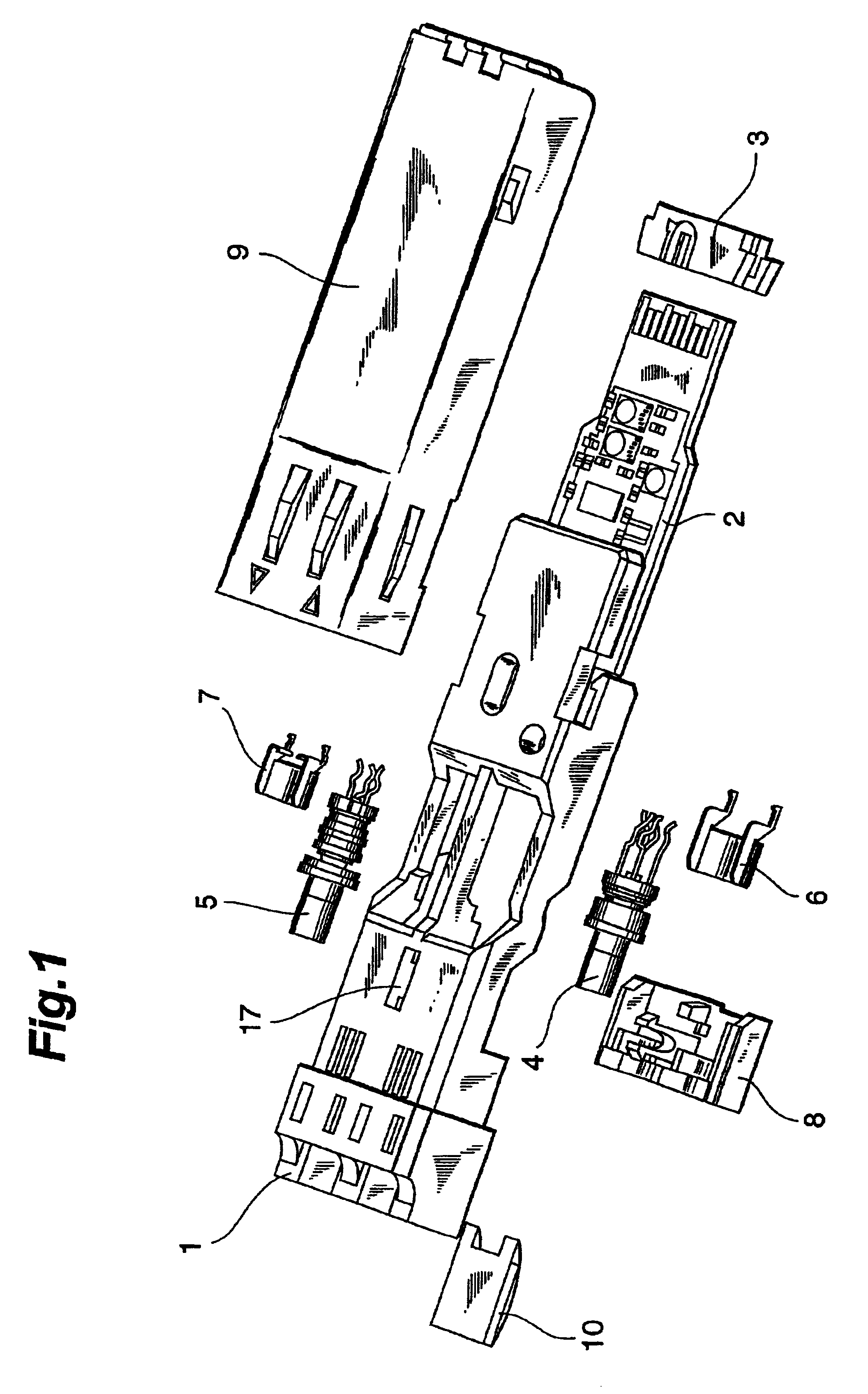
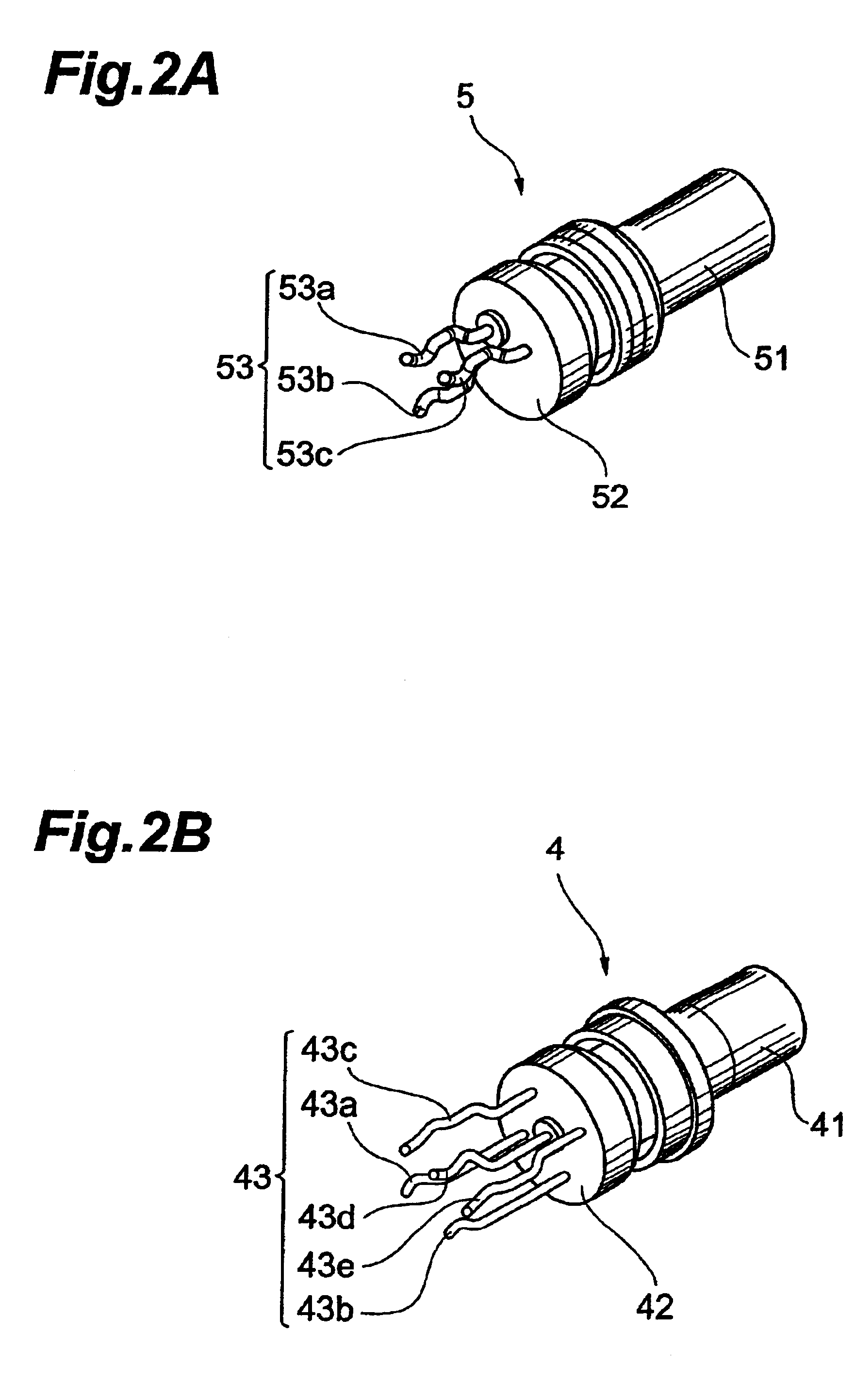
A wiring pattern of a circuit board comprises two reference voltage lines holding a signal line therebetween, whereas the reference voltage lines on both ends are electrically connected to a conductive bracket. The bracket covers and electrically shields lead pins connecting a light-receiving device unit or light-emitting device unit to the circuit board.

Description

1. Field of the InventionThe present invention relates to an optical module utilized in an optical transceiver and the like for linking and unlinking.2. Related Background ArtIn high-speed LANs (Local Area Networks), optical transceivers have widely been in use as a module for converting digital electric signals and optical signals to each other. In order to attain a higher density in ports of hub apparatus and the like using such optical transceivers, SFF (Small Form Factor) has been known as a unified standard enabling a smaller size. While such SFF optical transceivers are characterized by their small size and low power consumption, SFP (Small Form Factor Pluggable) optical transceivers making electric connectors attachable thereto and detachable therefrom without stopping devices have further been developed.As LANs attain a higher speed, digital signals transmitted by such an SFF or SFP optical transceiver have been shifting to a gigabit band. In the SFF or SFP optical transceiv...

Claims


Application Information

Patent Timeline
Patent Type & Authority Patents(United States)
IPC IPC(8): G02B6/42H01L31/0232H01S5/022
CPCG02B6/4246G02B6/4277
Inventor INUJIMA, TAKAYOSHIOKI, KAZUSHIGEKURASHIMA, HIROMITSUMURA, EIJI
Owner SUMITOMO ELECTRIC IND LTD
Learn More