Controller for limiting speed of robot component

a technology of robot components and controllers, applied in the direction of programmed control, programmed manipulators, instruments, etc., can solve the problem of strong pressing of operators, and achieve the effect of suppressing the influence of operators

Active Publication Date: 2020-07-14
FANUC LTD
View PDF36 Cites 3 Cited by
  • Summary
  • Abstract
  • Description
  • Claims
  • Application Information

AI Technical Summary

Benefits of technology

[0007]A robot device that perform an operation in collaboration with an operator can have the function for stopping a robot when the robot comes into contact with the operator. The influence on the operator can be suppressed by stopping the robot. For example, when robot arms are operated, the operator's hand may be caught between the arms. A robot controller can stop the motion of the arms by detecting contact between the robot and the operator.

Problems solved by technology

As a result, there was the problem that the operator is strongly pressed further in a period during which the robot is moved by inertia.

Method used


Image

  • Controller for limiting speed of robot component
  • Controller for limiting speed of robot component
  • Controller for limiting speed of robot component

Examples


Embodiment Construction

[0026]Referring to FIGS. 1 to 16, a controller for a robot according to an embodiment will be described below. The robot of the present embodiment is a robot that is capable of performing an operation in collaboration with an operator. Such the robot that is capable of performing an operation in collaboration with the operator is referred to as a collaborative robot.

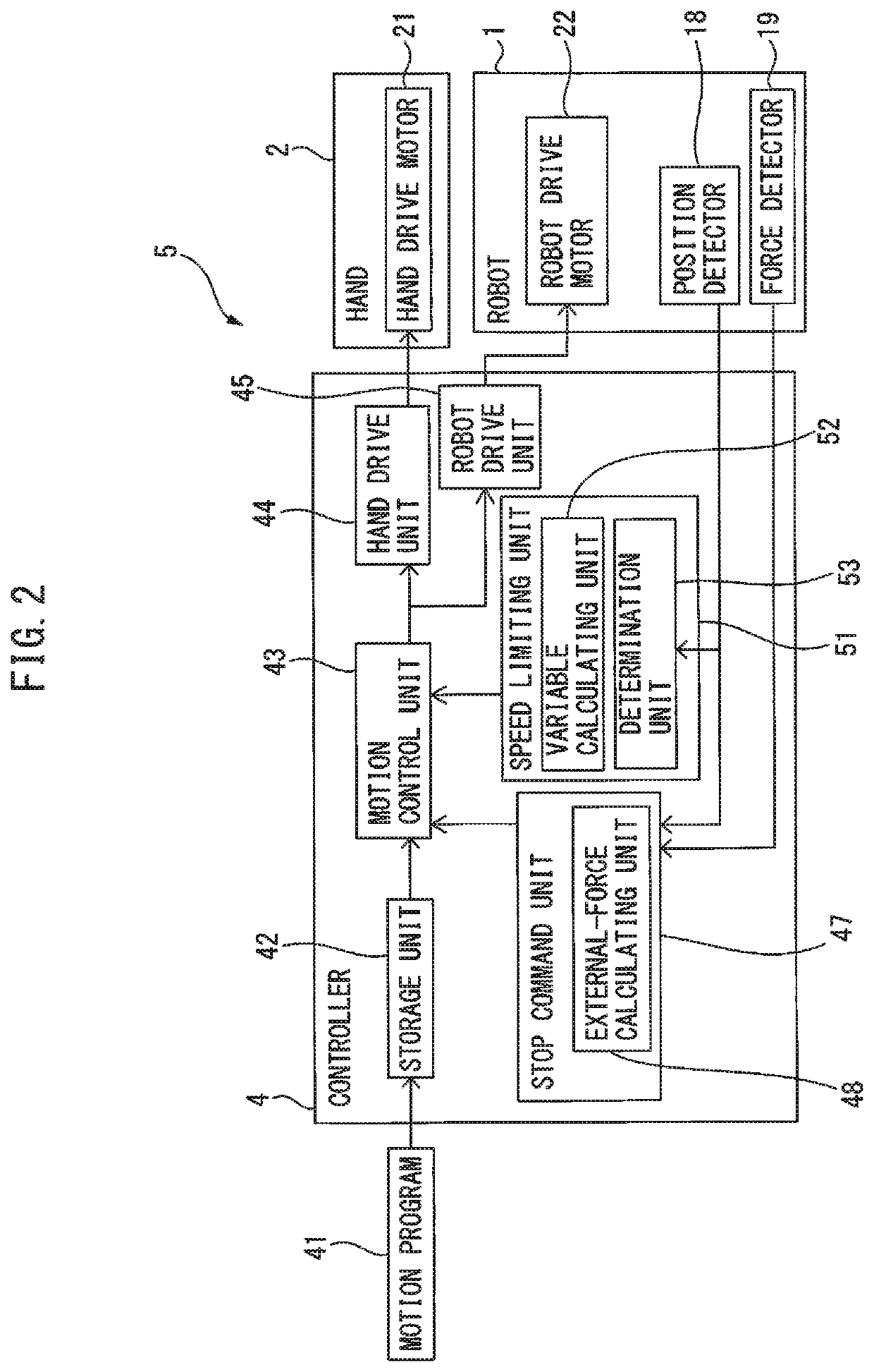
[0027]FIG. 1 is a perspective view showing a first robot device according to the present embodiment. A first robot device 5 includes a robot 1 and a hand 2. The robot device 5 includes a controller 4 that controls the robot 1 and the hand 2. The robot 1 of the present embodiment is an articulated robot including a plurality of joints. In the articulated robot, the orientations of arms and wrists are changed at the joints.

[0028]The hand 2 is an operation tool that grips and releases a workpiece 69. The operation tool is also referred to as an end effector. The hand 2 is formed so as to open and close claws 2a. The operati...


PUM


Abstract

A controller includes a stop command unit for stopping the motion of the robot when a person comes into contact with the robot, and a speed limiting unit for limiting the operation speed of the component driven on the drive axis. A variable calculated from the position of the component on the drive axis and the range of the variable in a state where the person is caught by the robot are determined in advance. The speed limiting unit acquires the variable from the output of a position detector and controls the operation speed of the component to a predetermined speed limit or lower if the variable is within the range.

Description

RELATED APPLICATIONS[0001]The present application claims priority of Japanese Patent Application No. 2017-195325, filed on Oct. 5, 2017, the disclosure of which is hereby incorporated by reference herein in its entirety.BACKGROUND OF THE INVENTION1. Field of the Invention[0002]The present invention relates to a controller for limiting the speed of a robot component.2. Description of the Related Art[0003]In the related art, for the safety of an operator, some measures have been applied in order to prevent an operator from entering a region around a robot during the operation period of the robot. For example, a safety fence is installed around a robot and limits the entry of the operator inside the safety fence during the operation period of the robot. Recently, a robot device that allow collaboration between the operator and the robot is known.[0004]In the robot device that allows collaboration with the operator, the robot can perform a task with the operator without the safety fence...

Claims


Application Information

Patent Timeline
Patent Type & Authority Patents(United States)
IPC IPC(8): B25J9/16B25J13/08G05B19/042
CPCB25J9/1676B25J9/1666B25J9/1635B25J9/1694G05B19/042B25J9/1664B25J9/1674B25J13/00B25J13/088
Inventor OYAMA, TAKUMIYAMAMOTO, TOMOYUKI
Owner FANUC LTD
Why Eureka
Try Eureka