
Suspended concrete flooring system and method

a technology of suspended concrete and flooring, applied in the direction of girders, walls, joists, etc., can solve the problems of high cost, high labor intensity, and many consumers forced to settle on suspended concrete floors,

Inactive Publication Date: 2004-06-29
JAMES HARDIE TECH LTD
View PDF10 Cites 24 Cited by
  • Summary
  • Abstract
  • Description
  • Claims
  • Application Information

AI Technical Summary

Benefits of technology

The system allows for easy manual installation, reduced labor and material costs, and increased structural strength, enabling faster construction and greater flexibility on sloped sites while maintaining the benefits of concrete flooring.

Problems solved by technology

This is often costly, and thus, suspended flooring systems offer an attractive alternative because the land does not have to be substantially altered before construction can begin.
Although consumers have expressed a preference for concrete flooring, many consumers are forced to settle on suspended floors constructed of wood because of its cost advantage over concrete suspended flooring.
Generally, suspended concrete floors are both material and labor-intensive and are thus often cost prohibitive regardless of the construction technique.
This results in a floor that is very heavy and therefore requires a significant amount of formwork to hold the floor in place.
Furthermore, the substantial amount of concrete results in a floor that is very expensive to install.
However, the substantial formwork necessary is labor intensive and usually makes this option cost prohibitive, especially for residential construction projects.
This method involves less supportwork than traditional poured floors; however, pre-cast slabs or beams are generally too heavy for manual installation and this technique often requires the use of heavy machinery, such as cranes, to position the heavy slabs into the framework, which makes construction projects on sloped construction sites problematic.
Not only are there additional costs associated with delivery of the slabs, but the additional handling of the cured slabs, (e.g. truck loading and unloading, lifting the slabs with a crane, positioning the slabs into the framework) presents opportunity for the slabs to become damaged.
Therefore, a significant amount of underlying supportwork is often required to provide adequate structural support for the floor during construction.
The installation of the supportwork, usually in the form of framework or formwork, in preparation for such a floor is a predominant component of the labor cost, and often makes large floors economically infeasible.
Accordingly, the ability to span a large area of floor with a minimum of supports during construction is a significant challenge in construction, and is a constant goal of suspended concrete flooring system design.
However, health risks associated with the manufacture of asbestos-cement based materials have restricted their use in recent years.
Asbestos-based cement composites also often exhibit brittle failure, while glass fiber reinforced cements are sensitive to age and curing, reducing the efficiency and desirability of these reinforcing agents.

Method used


Image

  • Suspended concrete flooring system and method
  • Suspended concrete flooring system and method
  • Suspended concrete flooring system and method

Examples


Embodiment Construction

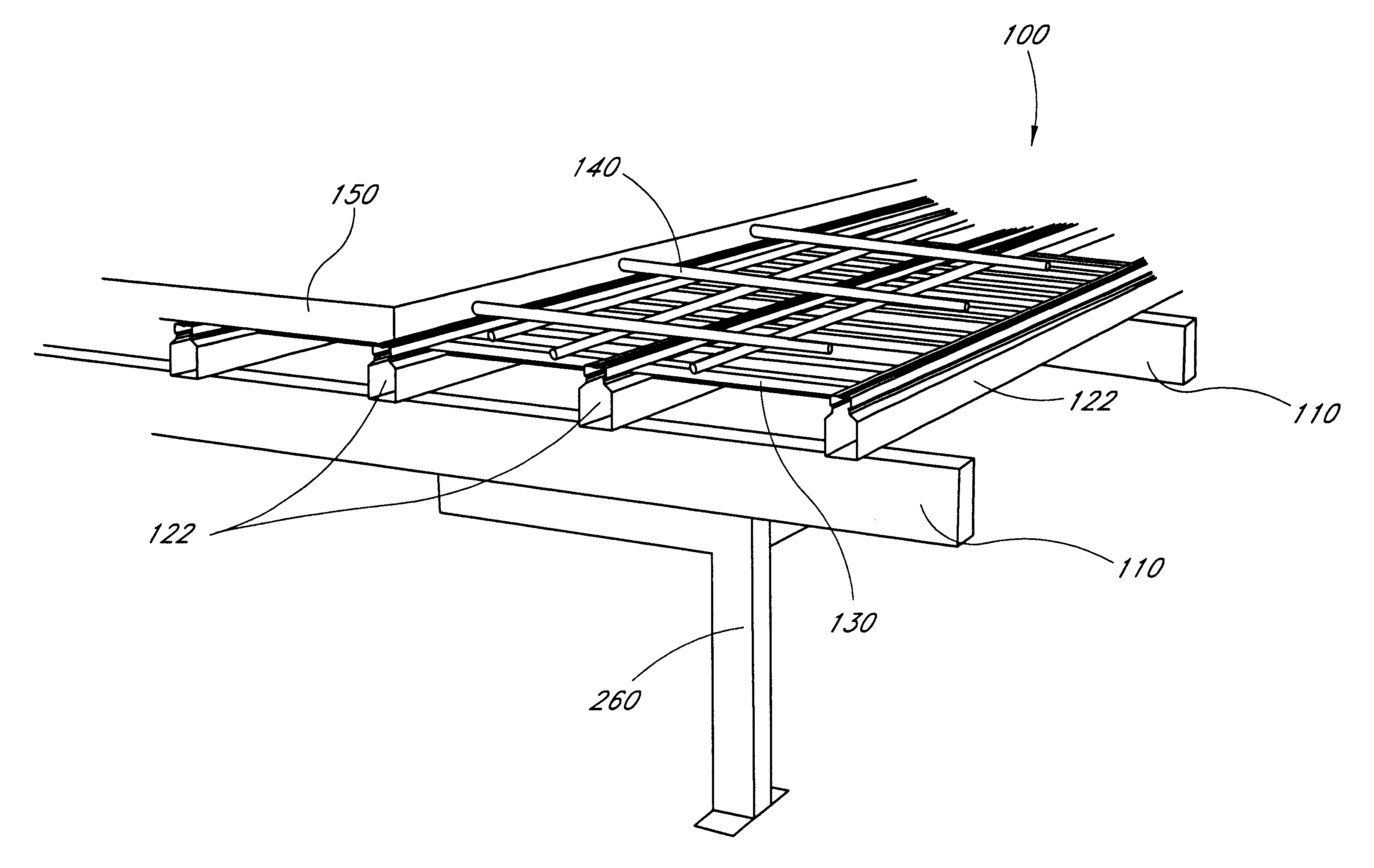
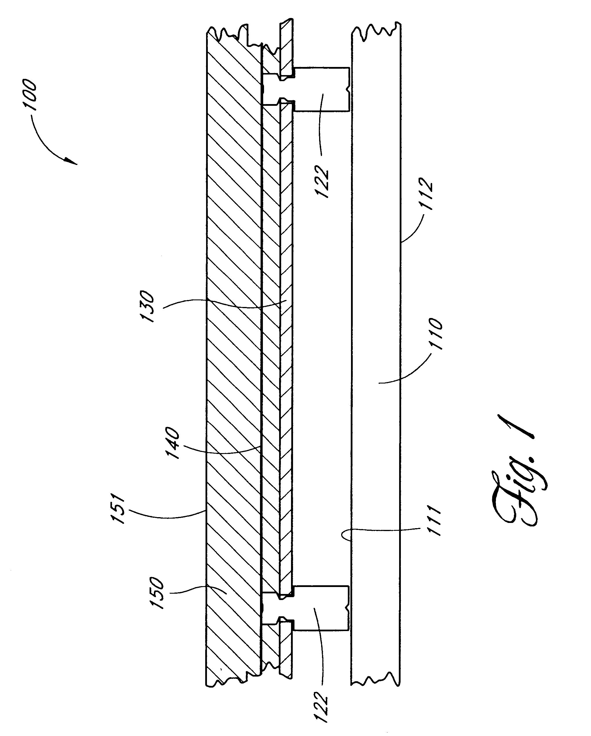
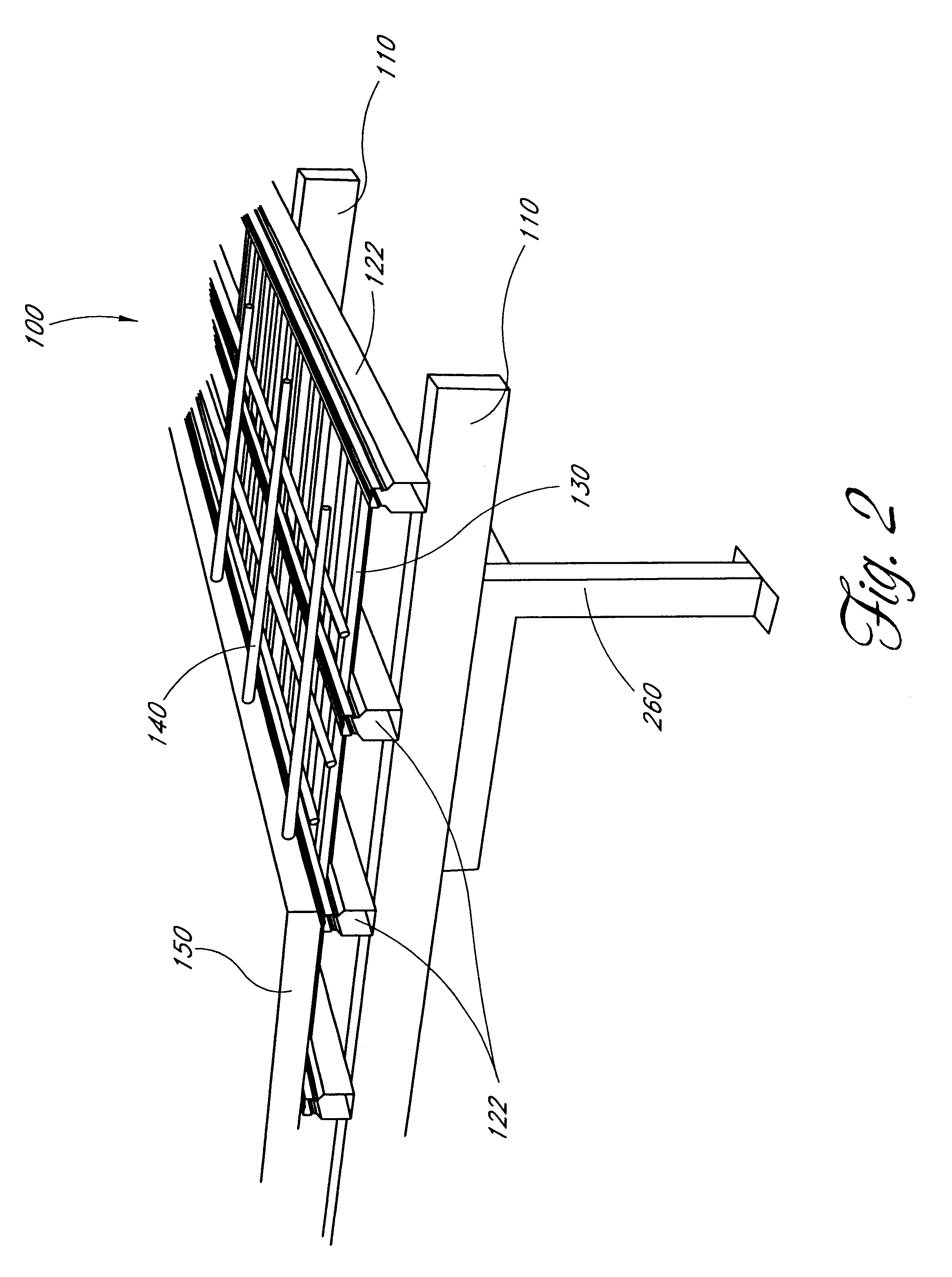
The preferred embodiments disclosed herein solve the above-described problems by combining, among other things, the prior art methods of positioning pre-cast concrete slabs or beams and pouring a floor in situ. Specifically, a pre-cast floor has the benefit of requiring a minimal amount of supportwork, while the poured floor offers the benefits of creating a monolithic floor without the need for slab transportation and heavy machinery installation. This is accomplished by making use of a rigid framework supporting corrugated fiber cement sheets to provide an underlying support layer for a poured in situ concrete floor. The framework includes strong, lightweight load-bearing members or supporting walls and joists arranged so as to allow for a large floor span between supports.

The result is a monolithic concrete floor that is easily constructed, can be installed manually without the need for large machinery, and can span larger unsupported distances thus reducing the necessary framewo...


PUM


Abstract

A suspended concrete flooring system (100) comprising a plurality of spaced-apart load-bearing members (110) or supporting walls that support a plurality of joists (122) having opposing sides and arranged substantially at right-angles to the load-bearing members. The joists have a support shelf (127) running the length of each opposing side for the purpose of supporting a plurality of fiber cement corrugated sheets (130) that span the space between the joists. A shrinkage control mesh (140) is arranged atop the corrugated sheets and is oriented generally in the direction of the load-bearing members and the joists. A thin layer of concrete (150) is formed over the corrugated sheets and the shrinkage control mesh, to form a flat, horizontal floor surface (151). The load-bearing members and the joists are made of strong, lightweight materials, such as steel. The combination of the light-weight structural materials, the fiber cement corrugated sheets, and the thin concrete layer allows for a suspended concrete floor system that is easily constructed and that has a relatively wide span as compared to conventional suspended concrete floor systems.

Description

1. Field of the InventionThe present invention relates to flooring systems, and in particular relates to suspended concrete flooring systems for use in residential and commercial construction projects.2. Description of the Related ArtSuspended flooring systems are gaining popularity for both residential and commercial construction projects. This is increasingly true for projects on sloped construction sites. Traditionally, a sloped site must be leveled by cutting away a suitable area for a foundation, and then erecting substantial retaining shoring to uphold the surrounding terrain. This is often costly, and thus, suspended flooring systems offer an attractive alternative because the land does not have to be substantially altered before construction can begin.Additionally, consumers have expressed a preference for concrete floors over wooden floors because of its smooth, flat surface that does not bow or warp, it is silent and does not squeak, it is fire resistant, and it is resista...

Claims


Application Information

Patent Timeline
Patent Type & Authority Patents(United States)
IPC IPC(8): E04C3/07E04B5/32E04B5/36E04C3/04
CPCE04B5/36E04C3/07E04C2003/0421E04C2003/043E04C2003/0465
Inventor EATON, PETER FRANCIS
Owner JAMES HARDIE TECH LTD
Learn More