
Method in drying of paper

a paper drying and paper technology, applied in the field of paper drying, can solve the problem of not being able to increase the temperature of the goods, and achieve the effect of saving space and simple structur

Inactive Publication Date: 2004-06-01
ANDRITZ TECH & ASSET MANAGEMENT
View PDF9 Cites 5 Cited by
  • Summary
  • Abstract
  • Description
  • Claims
  • Application Information

AI Technical Summary

Benefits of technology

A main object of the present invention is to provide a simple and space-saving method for drying of paper.
A third object of the present invention is to provide a method for fixed drying of paper.
A fourth object of the present invention is to provide a method for drying of paper with superheated steam instead of e.g. air, in which expected quality gains can be achieved without increased costs of installation and operation.
The present invention relates to a method in consolidation and drying of paper. A wet web is contacted with superheated steam, whose temperature is 200-600.degree. C., for the purpose of reducing, by heat transfer from the super-heated steam, the water content of the web by evaporation of a substantial part of the water in the same.

Problems solved by technology

In conventional drying it is not possible to increase the temperature of the goods to be dried above the wet temperature as long as "free water" exists.
The advantages of steam drying appear to be so obvious that it is strange that this method did not gain a considerable market share, but since this has not occurred, there must have been decisive difficulties, so that the advantages did not outweigh these additional problems.

Method used


Image

  • Method in drying of paper
  • Method in drying of paper
  • Method in drying of paper

Examples


first embodiment

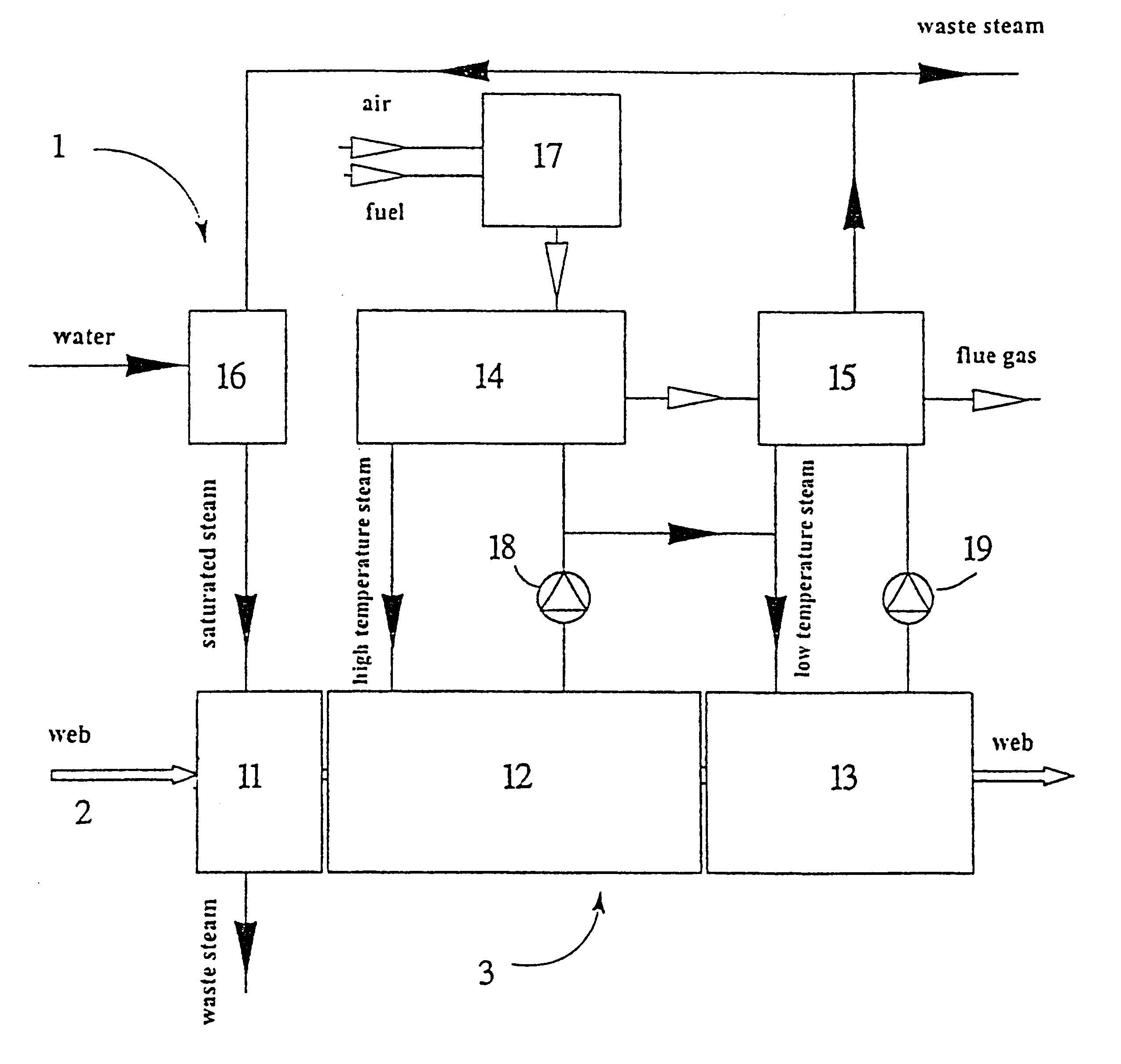
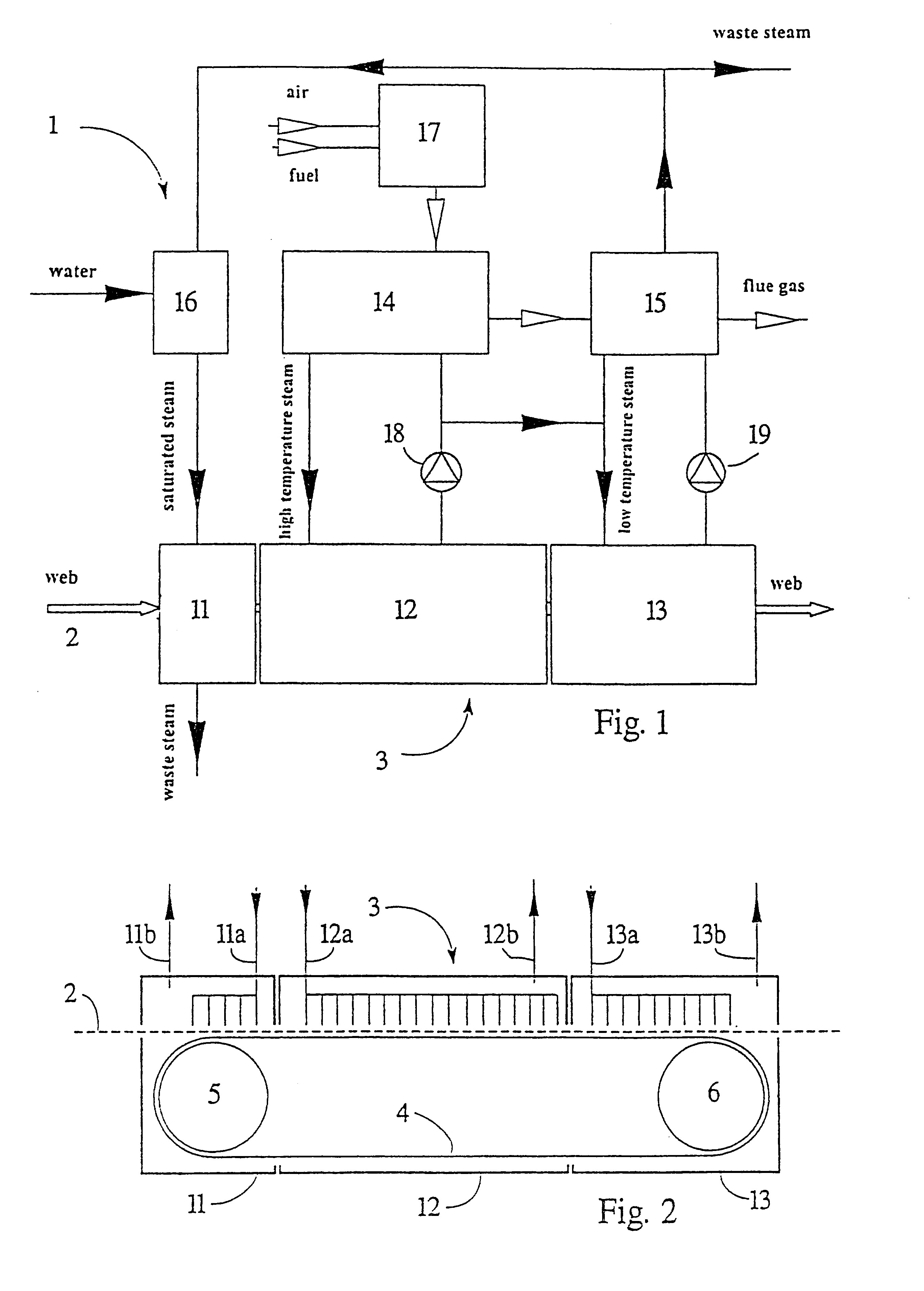
FIG. 2 is a schematic view of a first embodiment according to the invention of a treatment device 3 consisting of one preheating step 11 and two drying steps 12, 13. A web 2 is transported through all steps by means of a belt 4 of stainless steel running over two turning rolls 5 and 6. The preheating step 11 is provided with a nozzle system 11a for blowing saturated water vapour towards the web 2. Similarly, the two drying steps are provided with nozzle systems 12a and 13a for blowing superheated water vapour towards the web 2. The nozzle systems are, for the sake of clarity, drawn as tubing systems or the like. It goes without saying that they can be designed in many other ways, for instance as blow boxes or gaps. Used water vapour together with the steam that is being evaporated during drying is evacuated through conduits 11b, 12b and 13b.

second embodiment

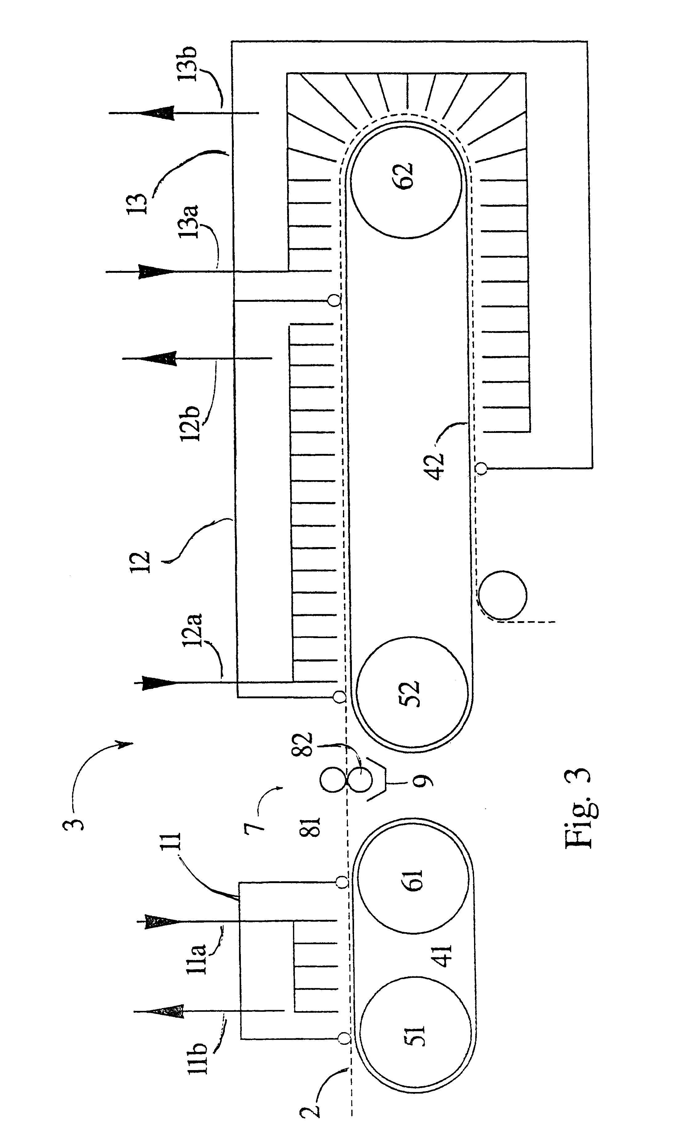
FIG. 3 is a schematic view of a second embodiment according to the invention of a treatment device 3 consisting of one preheating step 11 and two drying steps 12, 13. A web 2 is transported through the preheating step 11 by means of a first belt 41 of stainless steel running over two turning rolls 51 and 61. The web 2 is transported through the two drying steps 13 by means of a second belt 42 of stainless steel which runs over two turning rolls 52 and 62. Between the preheating step 11 and the drying step 12 there is a device 7 for mechanical dewatering, with two rolls 81 and 82 and subjacent means 9 for collecting press water. Steam is supplied and evacuated in the same way as in the embodiment according to FIG. 2.

In an exemplified embodiment of the invention, as described with reference to FIGS. 1 and 2, 25 t of paper an hour is dried in the treatment device 3, the pulp being based on completely dry substance. The dry content of the entering web 2 is 50%. In the preheating step 11...


PUM


Abstract

A method in consolidation and drying of paper. A wet web is contacted with superheated steam, whose temperature is 200-600° C. for the purpose of reducing, by heat transfer from the superheated stream, the water content of the web by evaporation of a substantial part of the water in the same. The wet web is supported and transported by means of a heat-conductive, gas-impermeable belt whose width is equal to or exceeds the width of the web, and jets of the superheated steam are directed towards the side of the web facing away from the belt.

Description

The present invention relates to a method in consolidation and drying of paper. A wet web is contacted with superheated steam for the purpose of reducing, by heat transfer from the superheated steam, the water content of the web by evaporation of a substantial part of the water.Drying of a web-shaped material, such as paper, usually occurs by the wet web being contacted with hot surfaces or by blowing a hot gas, preferably air, towards the web.In cylinder drying machines, the web-shaped material is heated by heated cylinders against which the web-shaped material is pressed by the web tension or by means of a felt or wire. The cylinders are heated by steam being supplied to their interior and condensing when contacting the casing of the cylinders. The condensate is evacuated continuously.Water is preferably drawn off in free ventilated draws between the cylinders. The ventilation air, or at least the major thereof, is drawn off from the casing which encloses the cylinder drying machi...

Claims


Application Information

Patent Timeline
IPC IPC(8): D21F5/00D21F5/18
CPCD21F5/00D21F5/18D21F5/185
Inventor ANDREN, ANDERSBACKA, STEFANEKH, JOHANFENG, XIAOLONGLILJENBERG, THOMASPERSSON, ULFZHANG, XIAOJING
Owner ANDRITZ TECH & ASSET MANAGEMENT
Learn More