
High-resolution high-speed NMR well logging device

a high-speed, logging device technology, applied in the direction of reradiation, measurement using nmr, instruments, etc., can solve the problems of slow logging process, low accuracy, and current methods of determining dip formation,

Inactive Publication Date: 2004-04-13
BAKER HUGHES INC
View PDF12 Cites 26 Cited by
  • Summary
  • Abstract
  • Description
  • Claims
  • Application Information

AI Technical Summary

Benefits of technology

The invention is about a new design for NMR tools used in oil well logging. The design is smaller and more energy-efficient than current commercial devices. It uses a permanent magnet to create a static magnetic field and a RF coil to induce a RF magnetic pulse. The device can measure properties such as porosity, permeability, and pore volume. The reduced size also allows for faster logging speeds and increased sensitivity. Overall, the invention improves the accuracy and efficiency of NMR tools in oil well logging.

Problems solved by technology

Secondly, since the magnetic moments are non-aligned with the static field, they experience a perpendicular force which causes them to precess around the static field.
Current methods of determining dip formation, such as electrical resistivity sensors, do not operate well in the presence of these oil-based muds.
In normal NMR procedures, the logging process is slower than more conventional methods.

Method used


Image

  • High-resolution high-speed NMR well logging device
  • High-resolution high-speed NMR well logging device
  • High-resolution high-speed NMR well logging device

Examples


Embodiment Construction

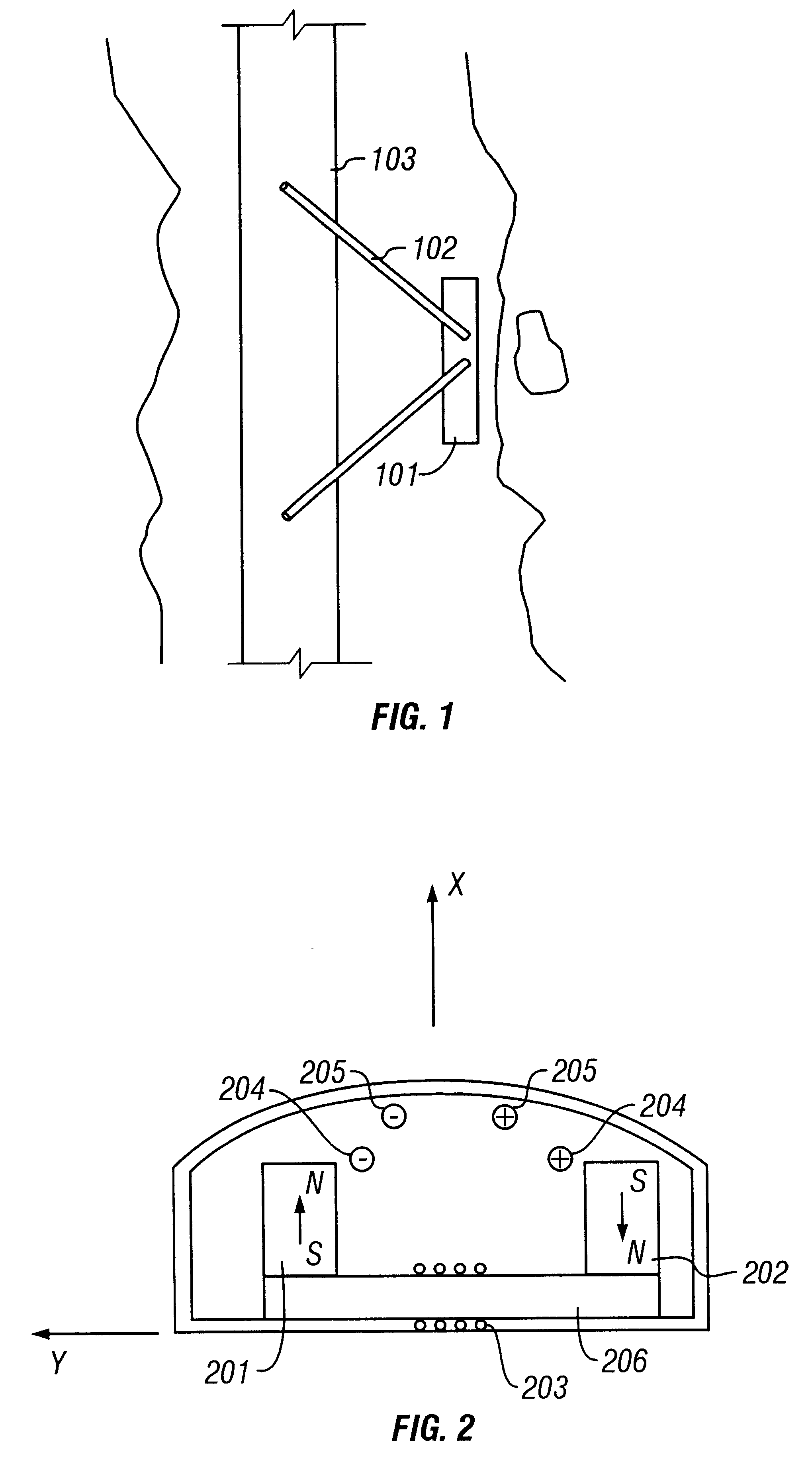
Referring to FIG. 1, the embodiment of the invention described herein is housed within a sensor assembly 101 which is attached by an arm mechanism 102 to the body 103 of the logging tool. The methods for attachment are the same as those which are commonly used in the well logging industry. The arm may be extended to make contact with the borehole wall using hydraulic, spring operated or electrical power. Although FIG. 1 displays only one sensor assembly, embodiments of the invention are not limited to only one sensor attachment. In fact, only the size of the sensor limits the number of sensors that can be used in a given embodiment.

As shown in FIG. 2, the sensor assembly comprises of a pair of magnets 201, 202 attached to an iron yoke 206, a transmitter coil assembly 204, a receiver coil assembly 205, and a coil 203 running lengthwise along the iron yoke. The coil 203 is intended to regulate the regions of magnetic field induced by the permanent magnets and may be referred to as a f...


PUM


Abstract

Wireline NMR well logging measurements suffer from disadvantages of poor vertical resolution, logging speeds less than 20 ft / min, and power consumption in excess of 200 W. In spite of these disadvantages, NMR well logging is used because it is capable of providing estimates for a number of petrophysical parameters that are difficult to obtain from other wireline data. These include estimates of the bulk volume irreducible (BVI) of fluids in the formation. The present invention targets BVI and clay bound water (CBW) measurements. Logging speeds of up to 60 ft / min are attainable with little or no loss of resolution. In one preferred embodiment, the tool has four sensors circumferentially distributed around the logging tool and in contact with the borehole wall. A horseshoe like magnet is used to generate the static magnetic field. The magnet poles are designed such that the magnetic field is uniform perpendicular tool motion, as well as provide a sufficiently large extent of the static field to provide polarization for bound water in rock formations. The RF portion of the sensor is comprised of at least one coil configured for transmission of an RF magnetic field into rock formations and at least two coils configured to separately receive the NMR signal from the formation. In another embodiment a coil is wound around the pole pieces or the iron yoke for the purpose of field shifting to enable acquisition of phase-alternated measurements.

Description

1. Field of the InventionThe invention is in the field of Nuclear Magnetic Resonance ("NMR") tools. More specifically, the invention pertains to new designs in NMR measuring devices in the application of oil well logging.2. Description of the Related ArtNuclear Magnetic Resonance has uses in many areas, including the fields of medicine, non-destructive testing, and in well logging in the oil exploration industry. In the well logging industry, NMR is used in determining properties such as porosity of the material, permeability, the bound liquid volume, the clay bound volume (CBW) and bulk volume irreducible (BVI), as well as formation type and oil content.A simple NMR device used in well logging uses a permanent magnet to apply a static magnetic field to a desired volume of investigation. Many magnet arrangements and field geometries have been proposed in prior art. In U.S. Pat. No. 4,350,955 to Jackson et al., two cylindrical magnets are placed end to end with north poles facing eac...

Claims


Application Information

Patent Timeline
Patent Type & Authority Patents(United States)
IPC IPC(8): G01V3/32G01R33/44G01V3/18G01R33/38G01R33/383
CPCG01N24/081G01V3/32G01R33/383Y02A90/30
Inventor EDWARDS, CARL M.GEORGI, DANIEL T.
Owner BAKER HUGHES INC
Learn More