Contact potential difference ionization detector

a technology of ionization detector and contact potential, which is applied in the direction of instruments, measurement devices, scientific instruments, etc., can solve the problems of limiting the speed of probe operation, capacitance probe, electric field,

Inactive Publication Date: 2004-04-06
GEORGIA TECH RES CORP
View PDF12 Cites 29 Cited by
  • Summary
  • Abstract
  • Description
  • Claims
  • Application Information

AI Technical Summary

Problems solved by technology

The difference in work function between the Kelvin probe surface and the testing surface results in an electric field when the two surfaces are in electrical contact.
However, this produces a "once only" measurement as the surfaces become charged, and the charge must dissipate before another measurement can be made.
Yet, there are several disadvantages with capacitance probes like the Kelvin probe as modified by Zisman.
One problem with the modified Kelvin probe is that the charge of the electrodes must be dissipated before another measurement can be made, which limits the speed of operation of the probe.
Another limitation of the modified or Kelvin type probe arises when used in a gas environment.
Measurement of the potential difference in a gas environment by capacitance probes presents problems of reproducibility because adsorption of gas on a surface can cause significant changes in the work function.
Another serious limitation of Kelvin type probes is the need for vibration of the probe.
The amplitude of vibration limits how close the probe can be placed relative to the testing surface.
Vibration of the probe also is a severe experimental constraints.

Method used


Image

  • Contact potential difference ionization detector
  • Contact potential difference ionization detector
  • Contact potential difference ionization detector

Examples


example ii

Use of the Ionization Probe as a Gas Flow Meter

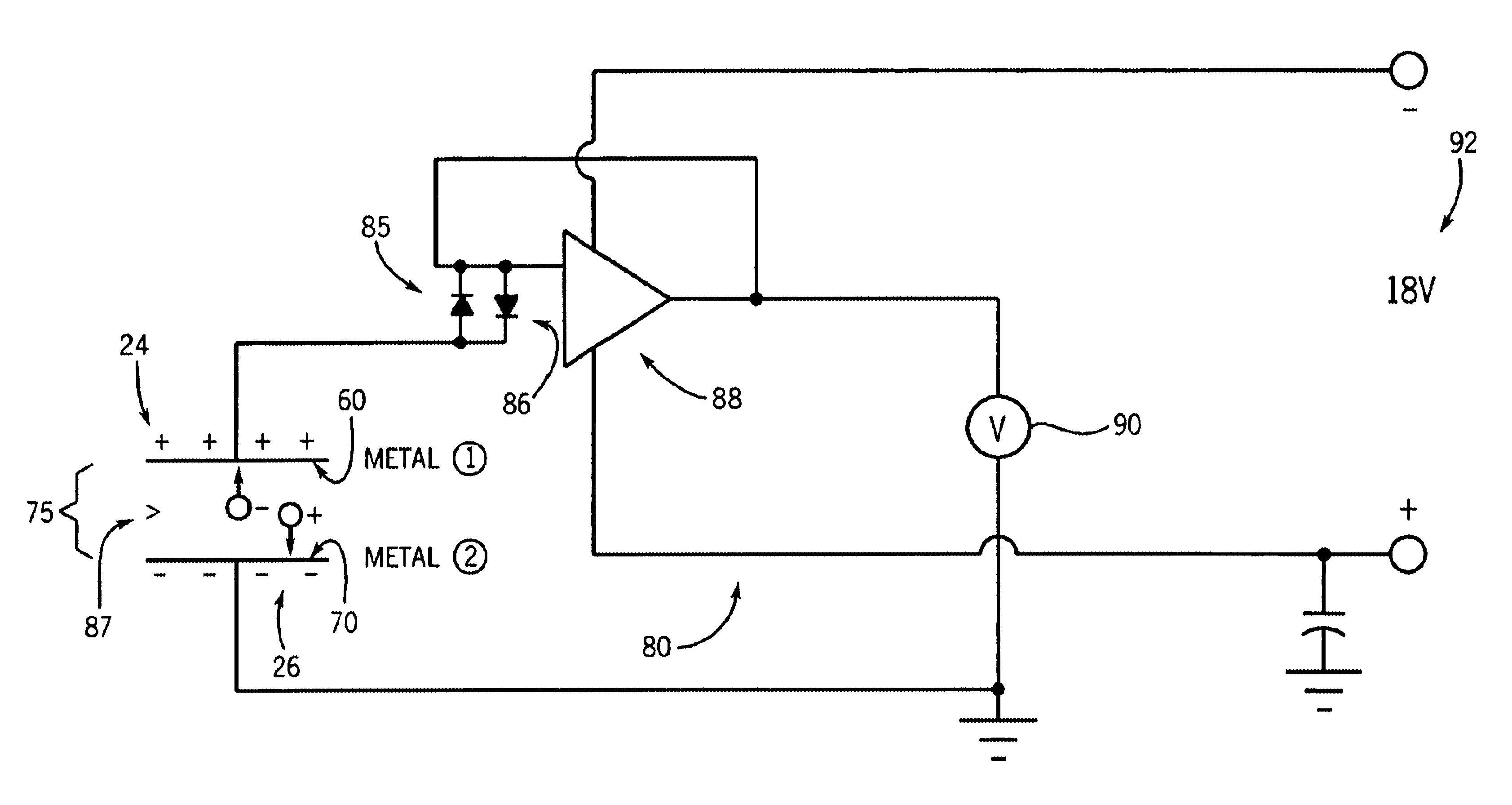
The ionization probe can further function as a sensitive gas flow meter. With the probe situated above a metal with a known work function (aluminum, for example) the voltage produced by the circuit will be related to the ionized gas in the gap between the probe and this metal (schematic of apparatus shown in FIG. 5). If the gas in the gap undergoes movement, then the voltage of the ion probe will change. The voltage is then a measure of the movement of the gas molecules in the gap. The sensitivity of the output voltage to gas movement was measured by an experiment where a gas flow was purposely produced, and the output voltage was measured as a function of the flow rate. The ionization probe was inserted into a glass tube, one end of which was connected to a dry air gas cylinder. A calibrated flow meter was used to measure the flow of the gas. The measurements of the ion probe voltage (V) and the gas flow rate (ml / min) is shown in FIG. ...

example iii

Ion Probe used as an Accelerometer

The ion probe can also be used as an accelerometer. By arrangement of an experiment as shown in FIG. 7 the ion probe is positioned above a surface whose spacing, d, and amplitude of vibration can be measured and controlled. In these experiments the voltage output of the probe can be demonstrated to be related to d, the spacing. FIG. 8 shows the voltage (V) versus spacing (mm) for six spacings ranging from 0.5 to 0.75 mm. As can be seen in this figure there is a reciprocal relationship between the voltage output and the spacing.


PUM

PropertyMeasurementUnit
voltageaaaaaaaaaa
work functionaaaaaaaaaa
electric fieldaaaaaaaaaa

Abstract

A nondestructive testing method of condensed matter surfaces, and a sensing device for the measurement of the work function of the surface of a conducting or semiconducting sample. The sensing device includes an ionization chamber, a probe having a first surface, and a potential difference measurement circuit that is capable of measuring a difference in potential between the first surface of the probe and a surface made of another material to be tested. The ionization chamber produces ionized particles that travel out of an output of the ionization chamber and toward the probe. The probe is a non-vibrating probe having a first surface that is either a positively or negatively charged electrode. The measurement circuit of the present invention is capable of sensing the small amount of electrical current that the electrons and ions moving toward the first surface and the testing surface represent.

Description

1. Field of the InventionThe present invention relates to a contact potential difference ionization detector and method of using such a detector to detect the work function of a surface, and more specifically to a probe for detecting chemical changes on surfaces.2. Description of Related ArtA Kelvin probe is a name given to a type of sensor that measures the difference in work functions between the probe surface and a surface of interest (the testing surface). This measurement is made by vibrating the probe and detecting an electrical signal related to the vibration frequency. The difference in work function between the Kelvin probe surface and the testing surface results in an electric field when the two surfaces are in electrical contact.The work function of the surface of an electronic conductor is defined as the minimum amount of work required to move an electron from the interior of the conductor to a point just outside the surface (beyond the image charge region). If an electr...

Claims


Application Information

Patent Timeline
Patent Type & Authority Patents(United States)
IPC IPC(8): G01N27/62G01N27/64G01N27/66
CPCG01N27/62G01N27/66
Inventor DANYLUK, STEVENZHARIN, ANATOLY
Owner GEORGIA TECH RES CORP
Why Eureka
Try Eureka