
Portable ramp

a folding ramp and ramp technology, applied in the field of folding ramps, can solve the problems of a risk of a dog's claw fastening in the joint region, the construction of foldable ramps is relatively heavy and difficult to handle, and the problem of known ramps/bridges of this nature are still encumbered with certain problems

Inactive Publication Date: 2004-04-06
LAGERGREN JULANDER ANITA
View PDF20 Cites 76 Cited by
  • Summary
  • Abstract
  • Description
  • Claims
  • Application Information

AI Technical Summary

Benefits of technology

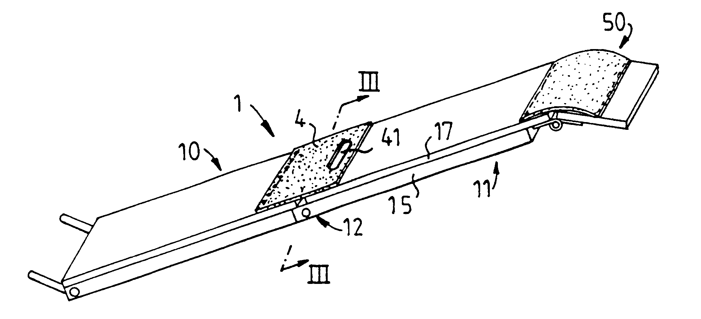
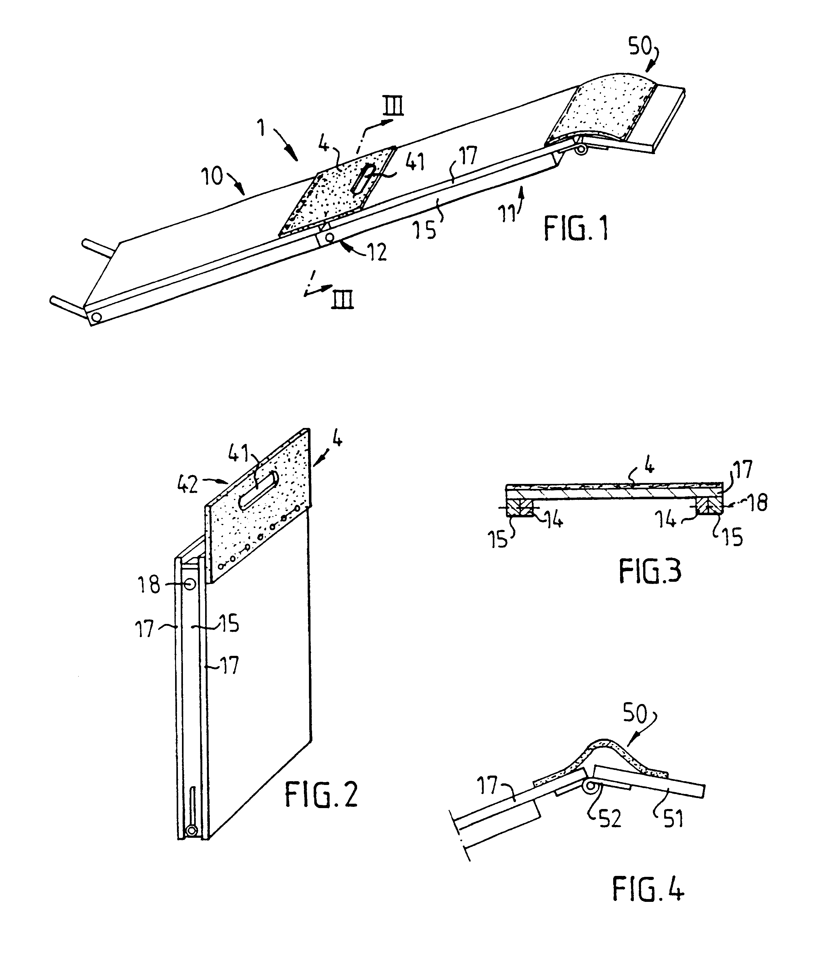
Basically, the joint between the unfolded or extended bridge parts is bridged by a tongue which extends over the width of the ramp and which is attached to one bridge part. The tongue is designed to lie in abutment with the other bridge part when the ramp is unfolded into its state of use. The tongue is preferably attached to that part of the ramp which is located lowermost in the sloping ramp when in use. When the ramp is folded up, so that the bridge parts are again generally parallel with each other, the tongue protrudes out beyond the end of the folded ramp. The tongue includes a through-penetrating opening. This opening defines together with the free edge-part of the tongue a handle which facilitates transportation / handling of the ramp and also facilitates handling of the ramp in conjunction with unfolding / folding of the ramp.

Problems solved by technology

However, known ramps / bridges of this nature are still encumbered with certain problems.
One problem is that the ramp is relatively heavy and difficult to handle, for example with respect to lifting the ramp into and out of the car and also with respect to folding-up and unfolding the ramp.
Another problem is that a foldable ramp construction constitutes a risk of a dog's claw fastening in the joint region between the outwardly folded parts of the ramp.
The consequences of such an occurrence are serious and the problem cannot therefore be ignored.

Method used


Image

  • Portable ramp
  • Portable ramp
  • Portable ramp

Examples


Embodiment Construction

Further scope of applicability of the present invention will become apparent from the detailed description given hereinafter. However, it should be understood that the detailed description and specific examples, while indicating preferred embodiments of the invention, are given by way of illustration only, since various changes and modifications within the spirit and scope of the invention will become apparent to those skilled in the art from this detailed description.

The ramp of the present invention comprises a bridge or overpass 1 that includes two parts 10, 11 which are interconnected by a hinge means 12. Each bridge part 10, 11 is comprised of two mutually parallel support bars 14 and 15, each supporting a respective plywood sheet 17. The sheet 17 is covered with matting (not shown) which functions to prevent the dog from slipping. The hinge means 12 is comprised of coaxial pivot shafts 18 which are positioned so as to enable the parts 10, 11 to be folded from an end position i...


PUM


Abstract

A ramp, for instance a walk ramp for pets, such as dogs, includes an elongated walk bridge (1) which is intended to be placed so as to slope between two height levels. The bridge includes two parts (10, 11) which are mutually sequential in the longitudinal direction of the bridge and which are mutually connected via a hinge means (18) which in one swinging direction has an end position in which the walk surfaces of said parts (10, 11) are essentially parallel and in a common plane, and which in its other swinging direction enable the parts (10, 11) to be folded to essential parallelity. When the bridge is extended or unfolded, a join gap between the parts (10, 11) on the upper load-carrying side of the bridge will be covered by a cover plate (4), which has an edge part that is fastened to one bridge part (10) and extends generally transversely over the width of the bridge (1). The opposite edge part of the cover plate (4) is free in the folded state of the bridge and projects out beyond the ends of said bridge parts (10, 11). The free edge part of the cover plate has an opening (41) which, when the bridge is extended or unfolded, is spaced from the join (17, 17) between parts such as to form a bridge carrying handle (42).

Description

1. Field of the InventionThe present invention relates to a portable ramp in the form of an elongated walk bridge that is intended to slope between two height levels and that includes two parts which are mutually sequential in the longitudinal direction of the bridge and which are mutually connected through the medium of a hinge member.The hinge has, in one pivotal direction, an end position in which walk surfaces of the parts are essentially aligned and in a common plane. In another pivotal direction, the hinge enables the parts to be folded essentially in parallel to each other. In the extended or unfolded state of the bridge, a cover plate covers a joint gap between the parts on the upwardly facing, load-carrying side of the bridge. The cover plate has an edge part which is fastened to one bridge part and which extends generally transversely across the width of the bridge.2. Prior ArtIt is well known that pets, such as dogs, sometimes find it difficult to jump from the ground up ...

Claims


Application Information

Patent Timeline
IPC IPC(8): B60P1/00B60P1/43B65G69/28B65G69/00
CPCB60P1/433B65G69/30
Inventor LAGERGREN-JULANDER, ANITA
Owner LAGERGREN JULANDER ANITA
Learn More