Alternating current driven type plasma display device
a plasma display device and alternating current technology, applied in the direction of discharge tube luminescnet screens, discharge tube/lamp details, gas-filled discharge tubes, etc., can solve the problems of reliability decline and reliability declin
- Summary
- Abstract
- Description
- Claims
- Application Information
AI Technical Summary
Benefits of technology
Problems solved by technology
Method used
Image
Examples
example 1
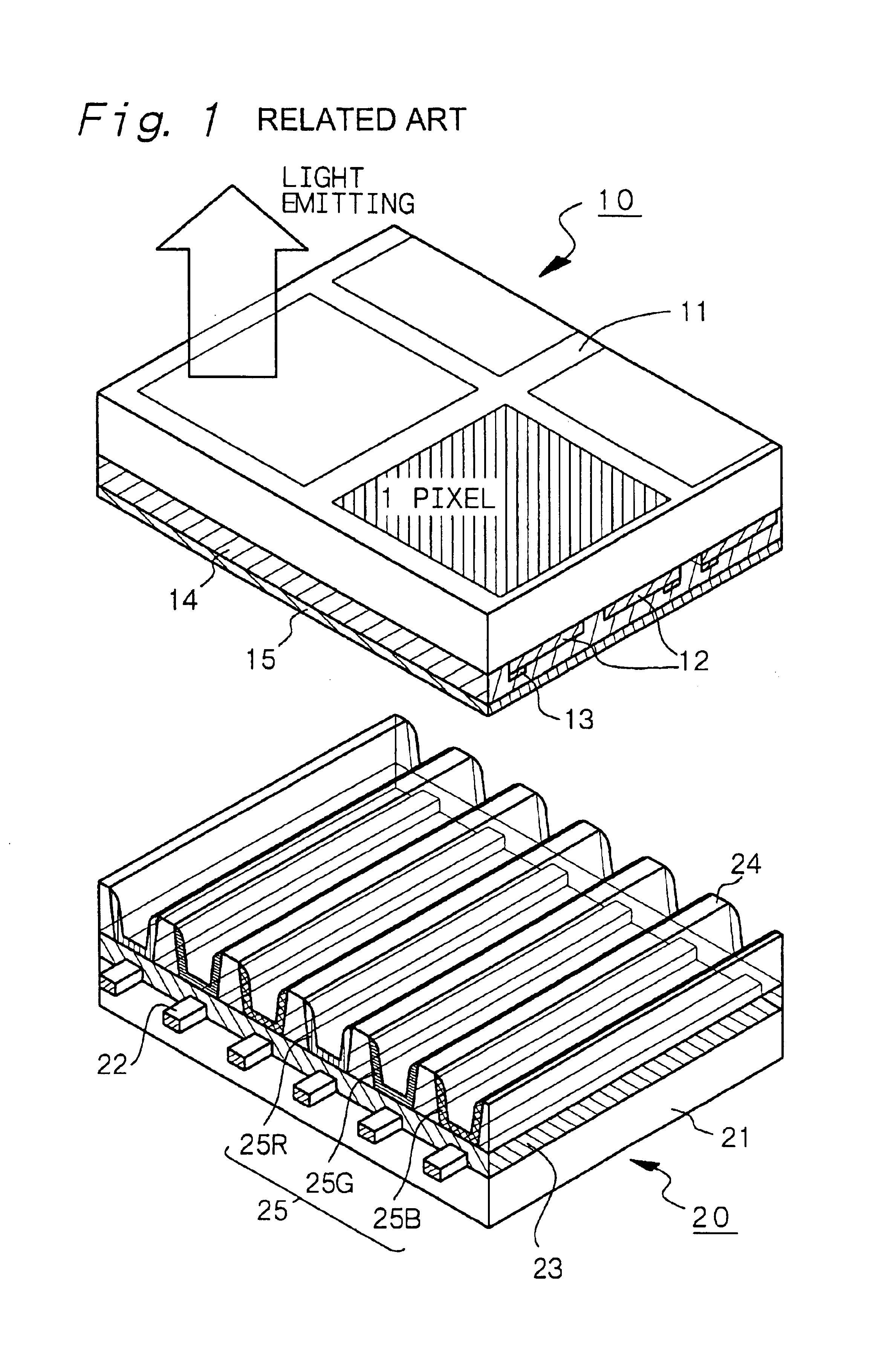
is concerned with the plasma display devices according to the first, fourth and fifth aspects of the present invention. Example 1 used the plasma display devices for testing in which the distance between a pair of the sustain electrodes 12 was constant or 20 .mu.m. Example 1 used a mixed gas of a xenon (Xe) gas as a first gas and a neon (Ne) gas as a second gas. While the Xe gas concentration was varied between 4% by volume and 100% by volume, the total pressure of the mixed gas was set at 5.times.10.sup.3 Pa (indicated by hollow squares in FIGS. 2 and 4), 1.times.10.sup.4 Pa (indicated by hollow triangles in FIGS. 2 and 4), 3.times.10.sup.4 Pa (indicated by solid circles in FIGS. 2 and 4) or 6.6.times.10.sup.4 Pa (indicated by hollow circles in FIGS. 2 and 4). The plasma display devices for testing under such conditions were measured for brightness. The voltage to be applied was set at an optimum level depending upon the total pressure in each gas mixture, and FIG. 4 shows the opti...
example 2
Example 2 used plasma display devices for testing in which the distance between a pair of the sustain electrodes 12 was 10 .mu.m, 20 .mu.m, 40 .mu.m or 70 .mu.m. And, the plasma display devices having a xenon gas pressure of 1.0.times.10.sup.4 Pa and a xenon gas concentration of 100% by volume were measured for brightness.
FIG. 5 shows results of the brightness measurement of the prepared plasma display devices. FIG. 5 clearly shows that the brightness tends to increase with a decrease in the distance between a pair of the sustain electrodes 12. That is, it is seen that when the distance between a pair of the sustain electrodes is less than 5.times.10.sup.-5 m, preferably less than 5.0.times.10.sup.-5 m, more preferably 2.times.10.sup.-5 m or less, higher brightness can be obtained.
Further, in cases using other discharge gases, that is, in the plasma display devices according to the second to fifth aspects of the present invention, similarly, the brightness tends to increase with a d...
example 3
Example 3 is concerned with the plasma display devices according to the first, second and third aspects of the present invention. Example 3 used plasma display devices in which the distance between a pair of the sustain electrodes 12 was constant or 20 .mu.m, and the discharge gas consisted of a xenon gas and a krypton gas alone.
FIG. 6 shows results of the brightness measurement of the prepared plasma display devices. The results shown in FIG. 6 are results of brightness measurements when the total pressure of the mixed gas of a xenon gas and a krypton gas alone was constant or 1.times.10.sup.4 Pa (10 kPa) and the concentration ratio of the Kr gas was varied between 0% and 100%. FIG. 6 clearly shows that the use of the mixed gas of a Xe gas and a Kr gas as a discharge gas gives a higher brightness than the use of a Xe gas alone or a Kr gas alone. Like the results shown in Example 1, further, the mixed gas of a Xe gas and a Kr gas give a higher brightness even when the total pressure...
PUM
 Abstract
Description
Claims
Application Information
 - R&D
- Intellectual Property
- Life Sciences
- Materials
- Tech Scout
- Unparalleled Data Quality
- Higher Quality Content
- 60% Fewer Hallucinations
Browse by: Latest US Patents, China's latest patents, Technical Efficacy Thesaurus, Application Domain, Technology Topic, Popular Technical Reports.
© 2025 PatSnap. All rights reserved.Legal|Privacy policy|Modern Slavery Act Transparency Statement|Sitemap|About US| Contact US: help@patsnap.com


