
Simplified buoyancy system for avoiding aircraft crashes

a simple and aircraft-based technology, applied in aircraft control, aircraft navigation control, aircraft components, etc., can solve the problem of saving expensive aircraft engine fuel, and achieve the effect of preventing air flow passag

Inactive Publication Date: 2004-03-23
GABRIEL EDWIN ZENITH
View PDF7 Cites 3 Cited by
  • Summary
  • Abstract
  • Description
  • Claims
  • Application Information

AI Technical Summary

Benefits of technology

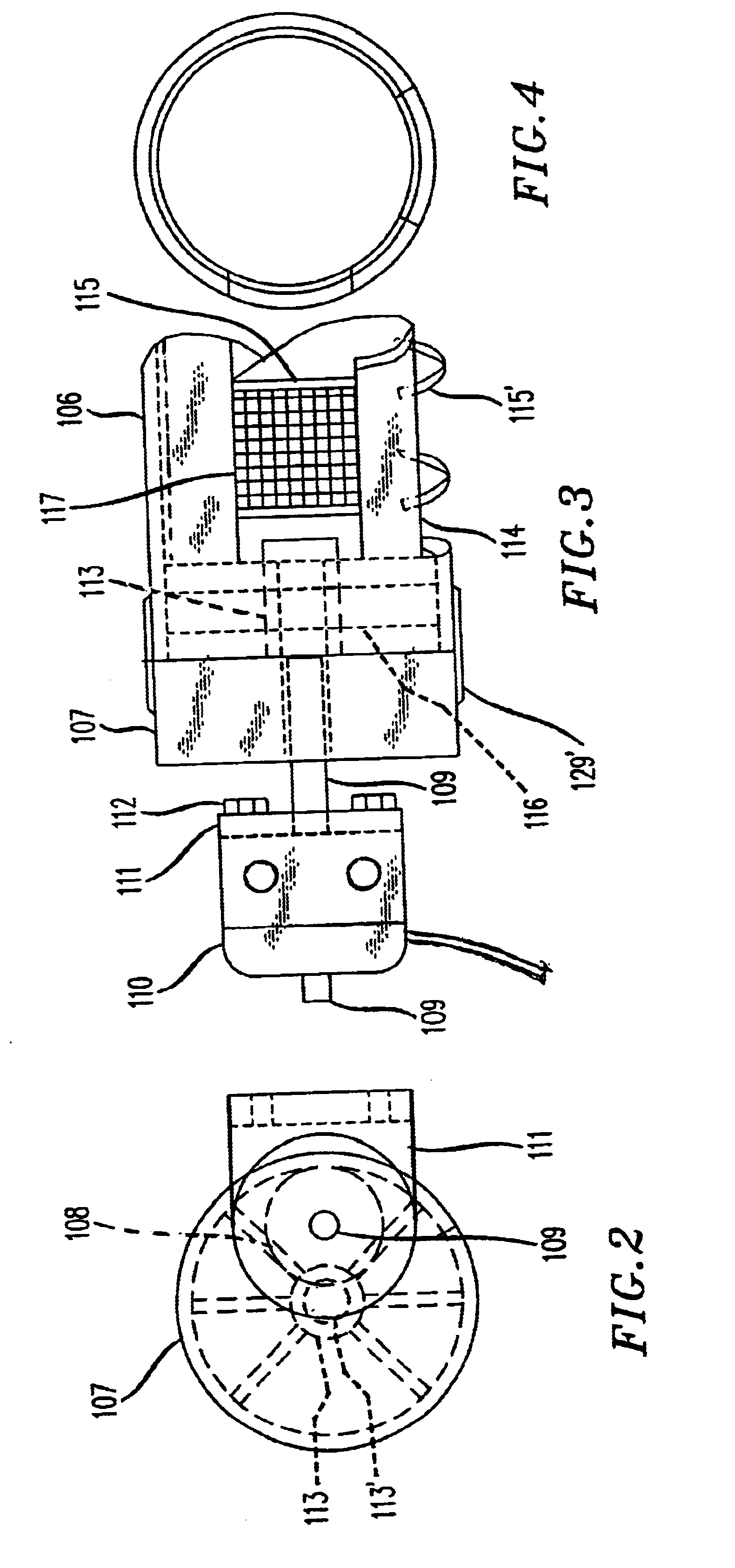
This is an additional novel technique for helping prevent light aircraft from crashing, should the aircraft experience engine or control system malfunction or pilot error. Instead of individual air valves, through which air blasts out, placed underneath the two wings of the aircraft, a plurality of elongated concentric coaxial tubings with elongated slots or openings are positioned underneath near the front edges of the wings. In one embodiment the outer tubing acts as a cover and rotates about the inner stationary tubing and is activated or operated by a prime mover which could be either an electric motor or rotary solenoid. The rotary motion of the outer concentric tubing is performed through a pair of pinion and internal spur gears, because of the convenience of coupling the rotatable internal gear to the outer tube. Both the inner and outer tubings have elongated openings or slots. When air is allowed to pass through the slots, the valve is in its open position and the openings of the inner and outer tubing align themselves. When it is desirable to prevent air from passing through, the electric motor or rotary solenoid rotates the outer tubing a prescribed number of degrees to close the inner openings, preventing air flow passage. Depending upon the length of an aircraft wing, more than one elongated tubing would be attached to each wing, since the geared motor is capable of rotating only a predetermined length of outer tubing comfortably, without jamming.
During aircraft take off, the tubing considered as elongated valves mounted on both wings, could be in their open positions, providing additional lift for the moving aircraft. Hence, expensive aircraft engine fuel may be saved.
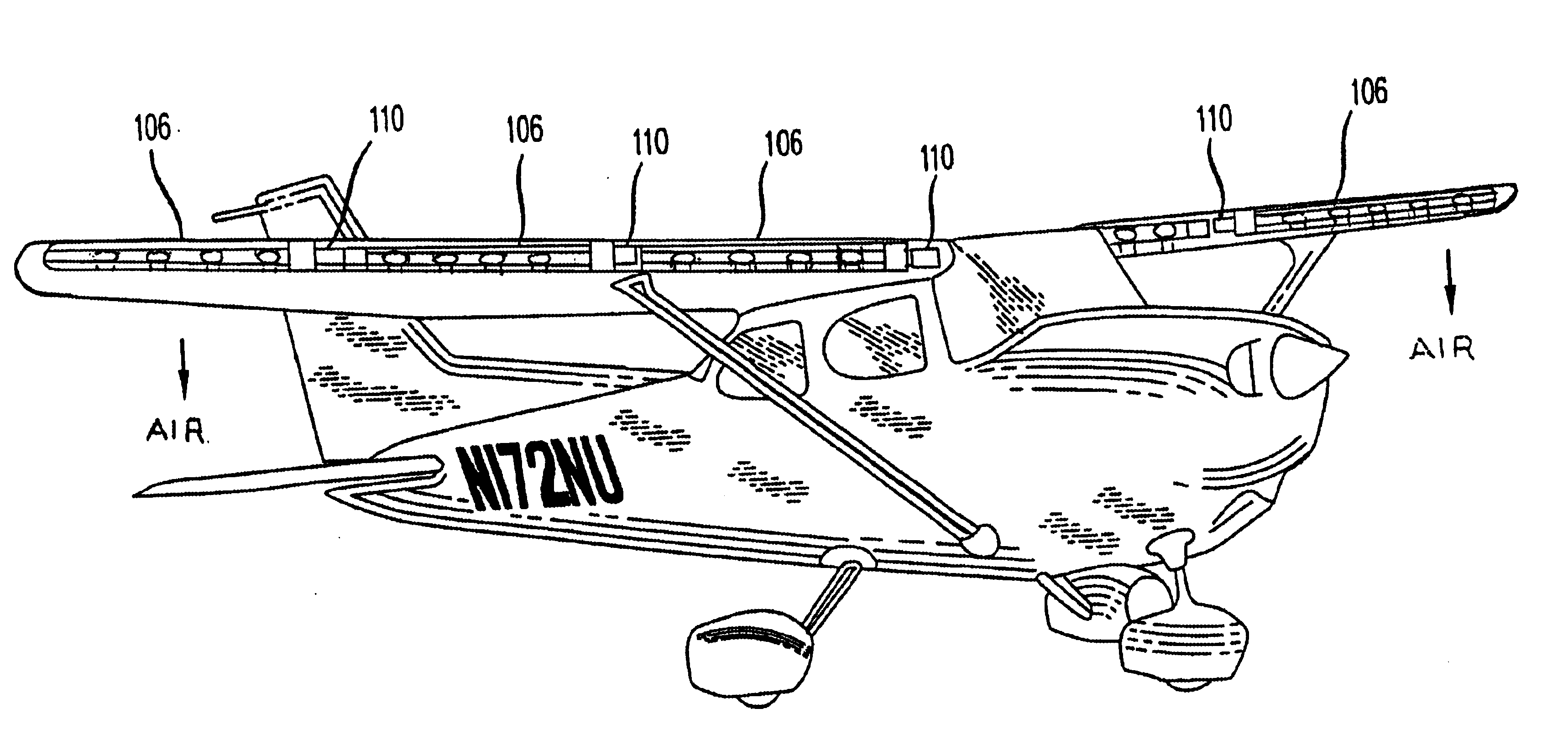
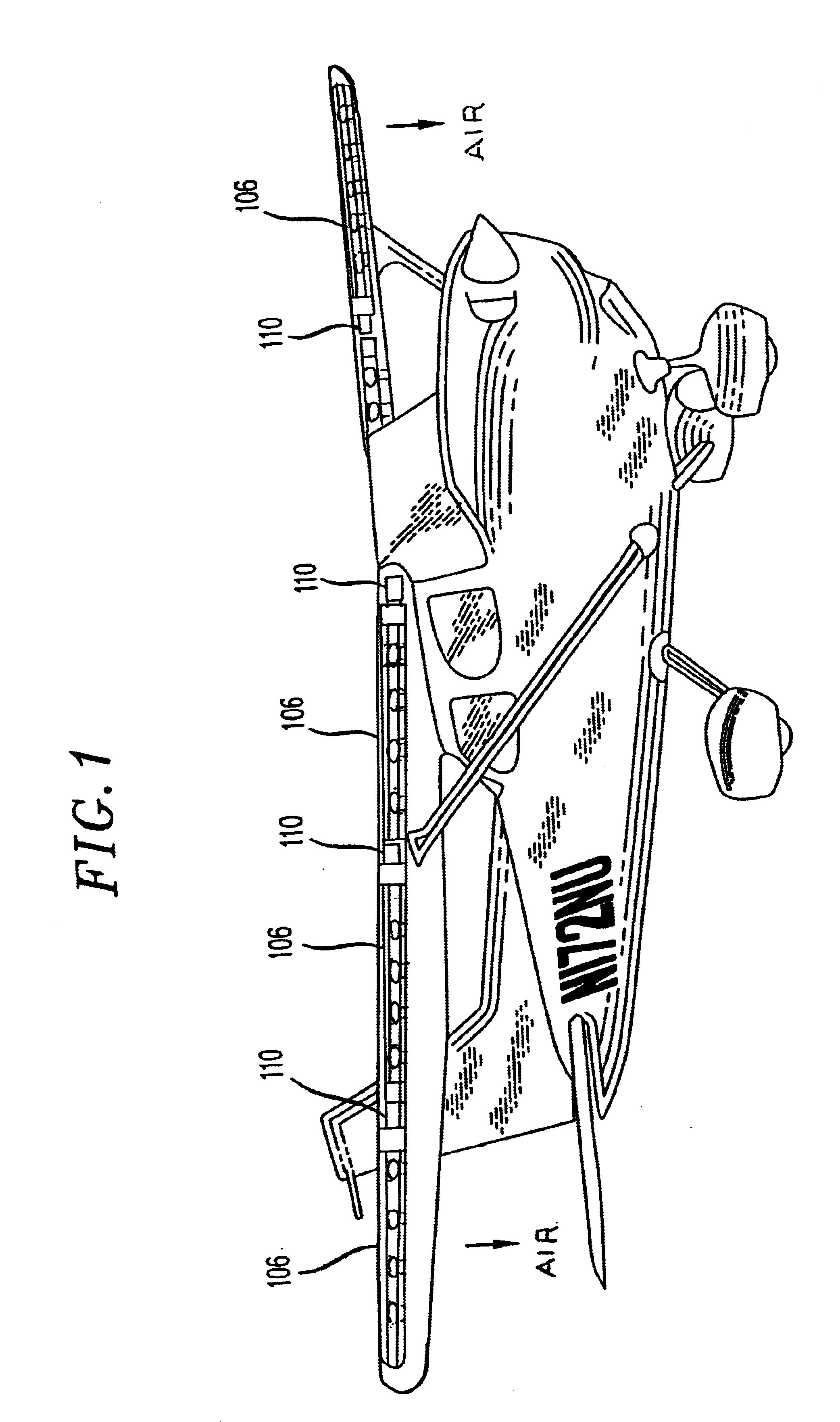
FIG. 1 shows a single-engine aircraft with several elongated, slotted tubing sections with apertures mounted in front of the wings of the aircraft, although they could be mounted underneath the wings for less visibility and less resistance to air flow.

Problems solved by technology

Hence, expensive aircraft engine fuel may be saved.

Method used


Image

  • Simplified buoyancy system for avoiding aircraft crashes
  • Simplified buoyancy system for avoiding aircraft crashes
  • Simplified buoyancy system for avoiding aircraft crashes

Examples


Embodiment Construction

This embodiment shown in FIG. 1 is presented as a technique using an elongated tubing with air valves not only to provide lift to a wing of an aircraft but also to enable the engine to save expensive aviation fuel on take-off from a runway, by providing such lifting. The lifting provided by elongated, slotted concentric tubing with windows as air inlets and air outlets also helps prevent the aircraft from crashing, by providing lift to a left or right wing that is turning in a downward direction too fast, beyond a predetermined allowable rate-of-turn, thus providing roll-angle control. The concentric tubings comprising the system is shown in FIGS. 2 to 9. In this configuration, the inner tubing 114 with circular or rectangular openings or windows 115 at right angles to each other is held rigid to the aircraft's frame by right angle brackets 118FIGS. 8 and 9. Outer tubing 106 is rotatable by prime mover 110', FIGS. 2 and 3. The prime mover's shaft 109 is attached to a pinion gear 108...


PUM


Abstract

This light aircraft crash avoidance system performs what previous such systems perform, but with much less system weight, much less cost and much less expenditure of electrical energy. In this system, air enters openings or windows in front of concentric tubing and leaves through openings facing vertically downward, thus giving lift to an aircraft's wing, where needed. Unlike other designs, this one requires no high-pressure air tanks to provide high pressure, high-velocity air to air valves. The valves depend upon the forward motion of the aircraft to provide high velocity air and lift. Two different prime movers are suggested for rotating the outer tubing for opening or closing the air valve, one being a d.c. motor and the other a rotary solenoid, as the simpler one to implement. The proposed design is for making any needed corrections to the aircraft's roll angle and for providing buoyancy to the entire aircraft when making a landing. A side benefit for this design is the ability for the aircraft's engine to save fuel on take-off and in flight, because of the added lift provided by the tubular air valves in their open positions. Openings or air outlets facing downward may be fitted with circular collars to assist in directing the high velocity out-flow air downward.

Description

1. Field Of The InventionThis invention is in the field of aircraft safety in flight, wherein even if the pilot were to make an error, the system will attempt to make the desired corrections to avoid and prevent the aircraft from going out of control and crashing. This disclosure with illustrations describes how the system functions to prevent an aircraft crash, by continually making any corrections to the aircraft's malfunctioning control system to keep the aircraft aloft, until it can be safely landed.2. Description of Prior ArtThe inventor is aware only of his own U.S. patent applications. The serial numbers of his applications are Ser. No. 09 / 366,262, filed Aug. 2, 1999, Ser. No. 09 / 470,737, filed Dec. 23, 1999, Ser. No. 09 / 514,125, filed Feb. 28, 2000.SUMMARY OF THE APPLICATIONThis is an additional novel technique for helping prevent light aircraft from crashing, should the aircraft experience engine or control system malfunction or pilot error. Instead of individual air valves...

Claims


Application Information

Patent Timeline
Patent Type & Authority Patents(United States)
IPC IPC(8): B64C15/00B64C15/14B64D25/00
CPCB64C15/14B64D25/00
Inventor GABRIEL, EDWIN ZENITH
Owner GABRIEL EDWIN ZENITH
Learn More