
Imaging apparatus

Inactive Publication Date: 2004-02-03
BRITISH TELECOMM PLC
View PDF46 Cites 49 Cited by
  • Summary
  • Abstract
  • Description
  • Claims
  • Application Information

AI Technical Summary

Benefits of technology

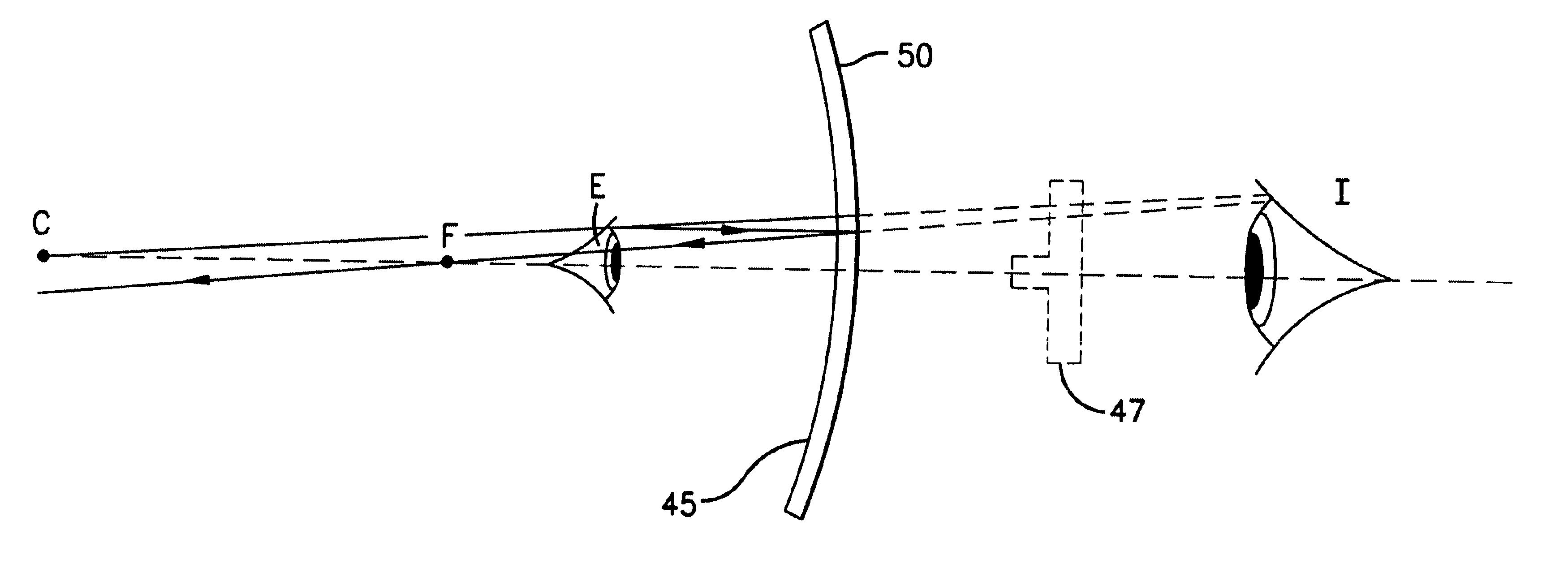
By providing a visible light reflector which is arranged to present a positive visual indication to the user that he or she is within a preferred range of distances from the camera, feedback is provided to the user enabling him to position his head at a correct distance from the apparatus. The visible light reflector provides this feedback as effectively as known devices but more cheaply than has hitherto been possible. The provision of such a visible light reflector reduces the need for a camera with an auto-focus (and possibly auto-zoom) facility. Furthermore, by arranging the reflector to lie on optical path between the user and the camera, the apparatus is made more compact than known apparatuses. The reflection provides a positive indication in the sense that there is some indication other than the user being able to judge his distance from the camera owing to perspective.
Preferably, the reflector comprises a non-planar reflector, the surface of which is shaped so as to present said positive visual indication. The advantage of such visible light reflectors is that they comprise few components and hence are inexpensive to manufacture.
Some embodiments of the present invention use a camera which is responsive to light outside the visible portion of the electromagnetic spectrum. For example, the camera used may responsive to infra-red light, in which case the reflector used can be a wavelength-selective mirror, which reflects visible light but allows the passage of infra-red light, placed in the aperture in the housing. It will be appreciated that this arrangement allows infra-red light reflected from the user's face to pass through the mirror and continue along an optical path towards the camera.

Problems solved by technology

Because of safety constraints on the level of illumination of the human eye, the depth of focus of the apparatus is limited and the user must position his head within a relatively narrow range of distances from the apparatus.
The cost of the LCD display in the above apparatus is significant.
Although the use of iris recognition technology is clearly desirable because of the high level of security it affords, the current cost of iris recognition units hinders their incorporation into credit card payment terminals and the like.
Although this relaxes the constraints imposed on the distance between the user and the apparatus, it does not provide a facility for aligning the eye within the field of view of the camera.
The use of such devices markedly increases the unit production cost of the imaging component of the iris recognition apparatus.
The user is, of course, able to estimate his distance from the apparatus owing to its apparent size (i.e. owing to perspective), but that is not a sufficiently accurate indication to enable him reliably to adopt a preferred position in relation to the apparatus.
This has the result that the reflection seen by the user undergoes changes in both size and orientation as the user approaches the apparatus.

Method used


Image

  • Imaging apparatus
  • Imaging apparatus
  • Imaging apparatus

Examples


second embodiment

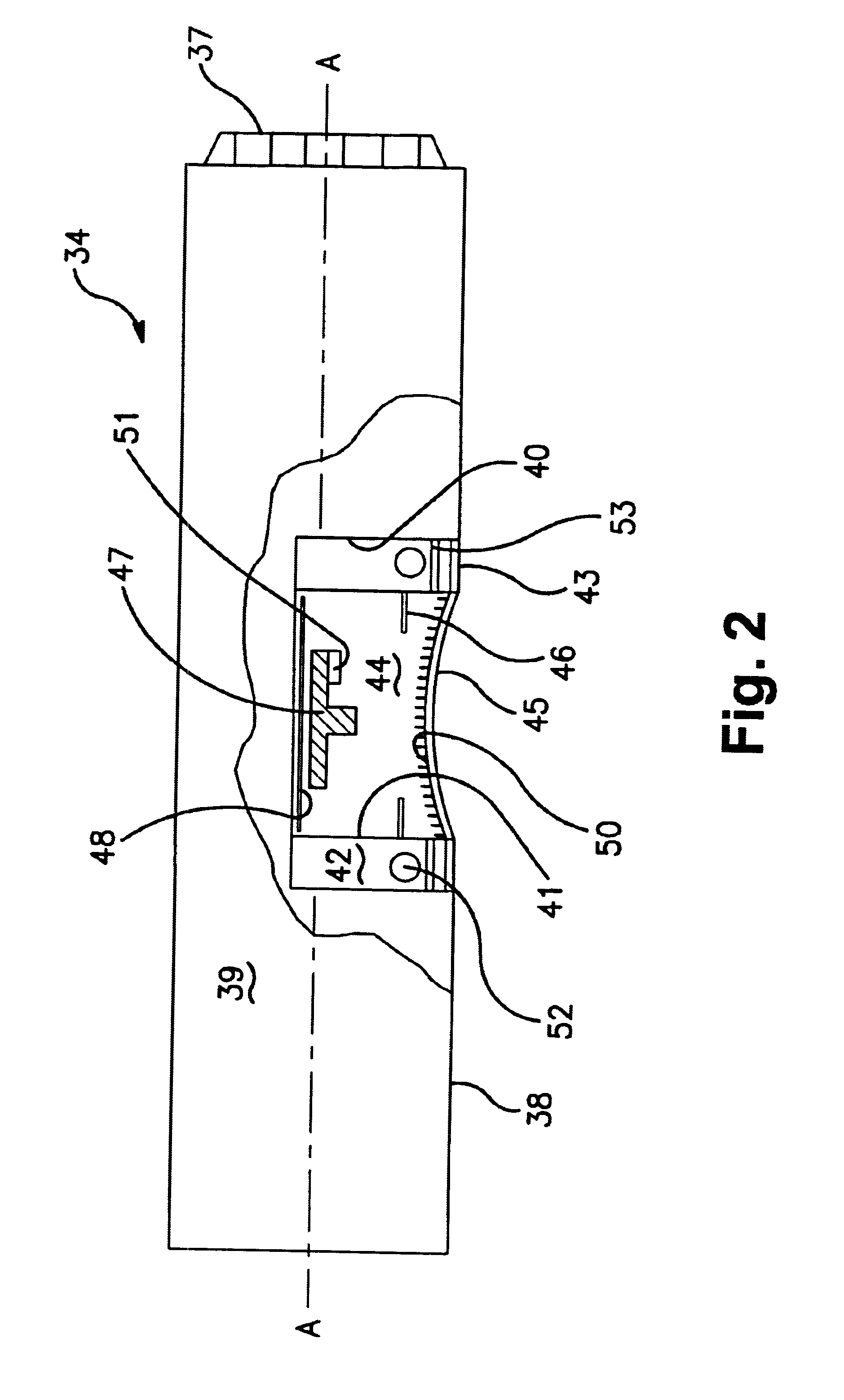
In the present invention, additional guide markings are painted on the front surface of the curved mirror 45. The guide markings comprise the central sections of the sides of a horizontally oriented 30 mm*20 mm rectangle centred at the centre of the mirror 45.

first embodiment

The use and operation of the apparatus are as described in relation to the first embodiment save for the following points. In addition to the prompt issued by the kiosk requesting the user to move forward until he sees a right way up reflection (I) of his eye, the user is further prompted to move to a distance such that the outer boundaries of the reflection of his eye (I) correspond as closely as possible to the guide markings. Not only does this encourage the user to align his eye centrally in the field of view of the camera, since the size of the reflection (I) of the user's eye varies with distance from the mirror 45, it further results in the user being guided to a more tightly defined preferred distance from the camera 47.

third embodiment

the present invention is illustrated in FIGS. 4A and 4B.

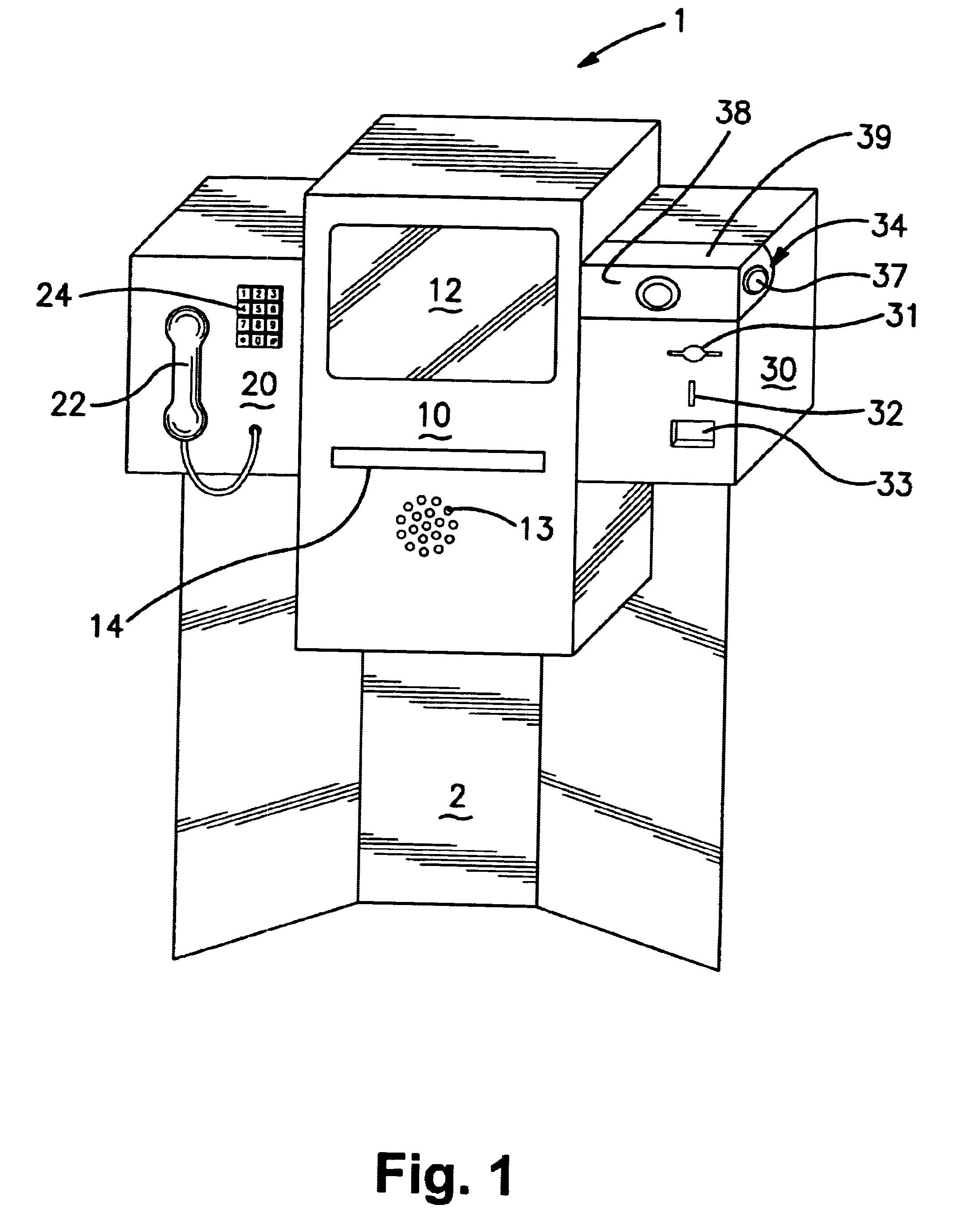
Some multimedia kiosks provide a video-conferencing facility so that the user may have a video-conference with, for example, a sales assistant at the store from which he wishes to buy something. In this case, using only a single camera for both the video-conferencing and the iris recognition enables both the design and the use of the apparatus to be simplified.

The problem that then faces the designer is that video-conferencing cameras often cannot provide an image of an object close to the camera, which image is both focused and magnified to the degree required for iris recognition.


PUM


Abstract

An imaging apparatus suitable for capturing a image of one or more of a user's facial features is disclosed. The apparatus includes a spherical cold mirror which presents a concave surface to the user and is disposed between the user and the camera. The user is able to conclude that he is close enough to the camera for successful image capture when the reflection he sees in the mirror is the right way up. In a preferred embodiment, markings are provided on the front surface of the mirror to aid the user in placing his eye within a predetermined range of distances from the camera. The imaging apparatus is suitable for use in iris recognition apparatuses and provides a relatively inexpensive alternative to known apparatuses.

Description

1. Field of the InventionThe present invention relates to an imaging apparatus. It has particular utility in relation to an imaging apparatus operable to obtain an image of one or more facial features of a user.2. Related ArtOne known apparatus of this type forms a component of the IriScan 2000 EAC.TM. iris recognition apparatus manufactured by lriScan Inc. The apparatus includes an image capture unit comprising a wall-mounted body portion which rotatably supports a tiltable housing containing the optical elements used in the apparatus. The camera and path-bending optics inside the housing are arranged so as to provide the camera with a view through an aperture provided in the front wall of the tiltable housing. The housing additionally contains a liquid crystal display (LCD display) which is viewed by the user during the iris recognition procedure through the same aperture. The LCD display is driven by the video signal which is currently being output by the camera.In using the appa...

Claims


Application Information

Patent Timeline
IPC IPC(8): A61B3/12A61B5/117A61B3/113A61B5/1171G06K9/00G06T1/00
CPCA61B5/1176G06K9/00221G06K9/00604G06V40/16G06V40/19
Inventor MCCARTNEY, DAVID JOHNSEAL, CHRISTOPHER HENRY
Owner BRITISH TELECOMM PLC
Learn More