
Nonlinear equalizer and decoding circuit and method using same

a decoding circuit and equalizer technology, applied in the field can solve the problems of significant reduction in signal amplitude, inability to sufficiently eliminate nonlinear isi in high density recording systems, and severe nonlinearity of digital magnetic recording systems

Inactive Publication Date: 2004-01-13
IBM CORP
View PDF6 Cites 11 Cited by
  • Summary
  • Abstract
  • Description
  • Claims
  • Application Information

AI Technical Summary

Benefits of technology

The present invention relates to a nonlinear equalizer and a decoding circuit for removing intersymbol interference in high-density recording systems. The nonlinear equalizer uses a signal conditioning algorithm to adjust a partial response sampled signal with four non-zero samples to produce a three-level signal. The decoding circuit includes an analog-to-digital converter, a linear equalizer, a nonlinear equalizer, and a partial response maximum likelihood detector. The nonlinear equalizer employs a signal conditioning algorithm to condition the partial response sampled signal with four non-zero samples to produce a plurality of samples, and if one sample is greater than 0.4 in absolute value, the magnitudes of samples may be decreased by a predetermined rate by adding a predetermined amount. The nonlinear equalizer is faster and requires less memory than conventional decoding circuits and is effective in reducing intersymbol interference. The decoding circuit may be used in a high-density recording system.

Problems solved by technology

Digital magnetic recording systems typically experience severe nonlinearity at high densities.
Adjacent transitions also tend to erase each other, causing significant reduction in the signal amplitude.
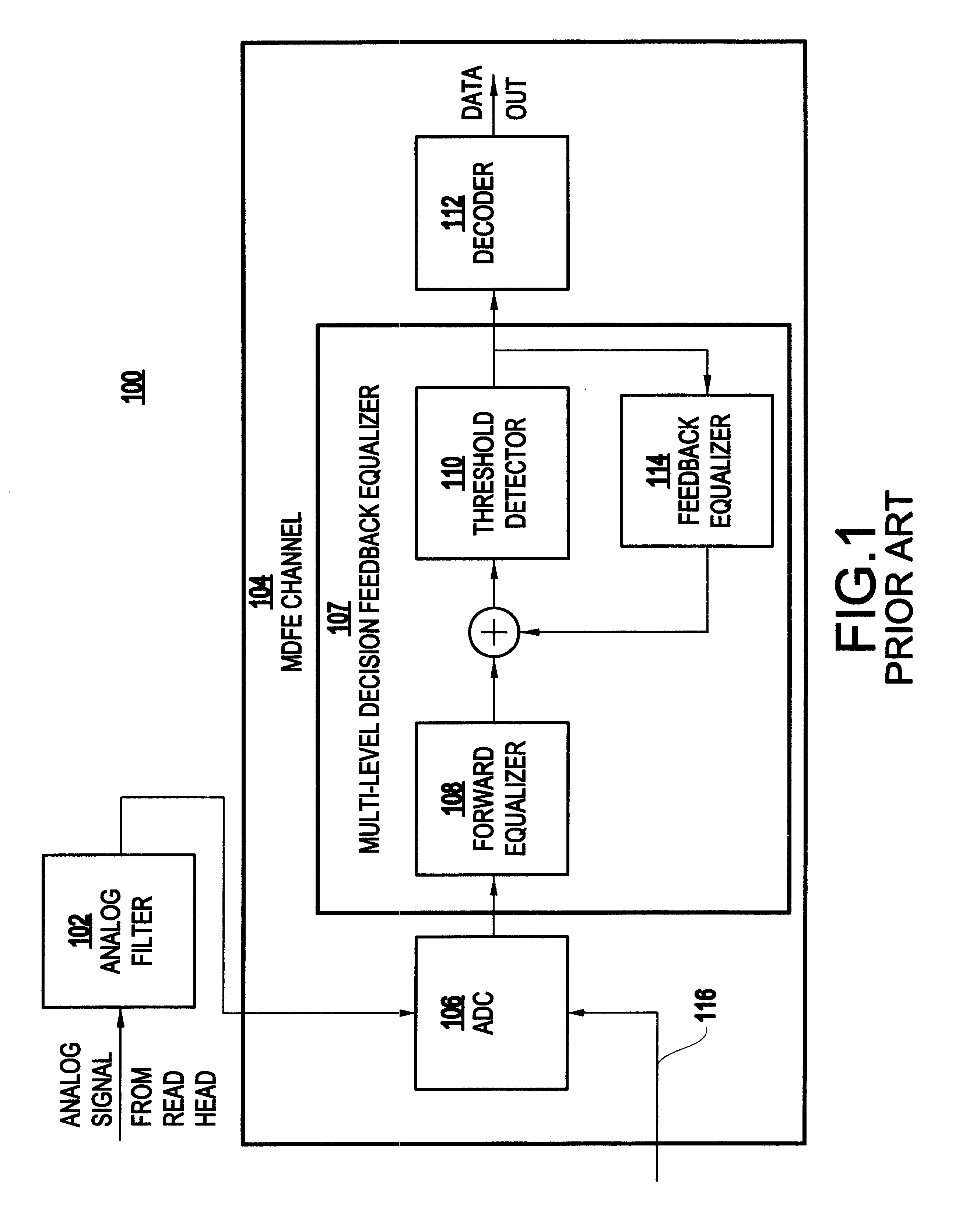
However, the feedback equalizer 114 cannot sufficiently eliminate nonlinear ISI in high density recording systems.
However, because the feedforward section of the RAM-DFE has the same structure as the conventional DFE, it is not effective in reducing the nonlinear ISI existing in the precursor part.
In addition, it requires a large memory of 2.sup.N (where N is the number of consecutive inputs) and the convergence speed is slow because of the search time needed for the look-up table filter.

Method used


Image

  • Nonlinear equalizer and decoding circuit and method using same
  • Nonlinear equalizer and decoding circuit and method using same
  • Nonlinear equalizer and decoding circuit and method using same

Examples


Embodiment Construction

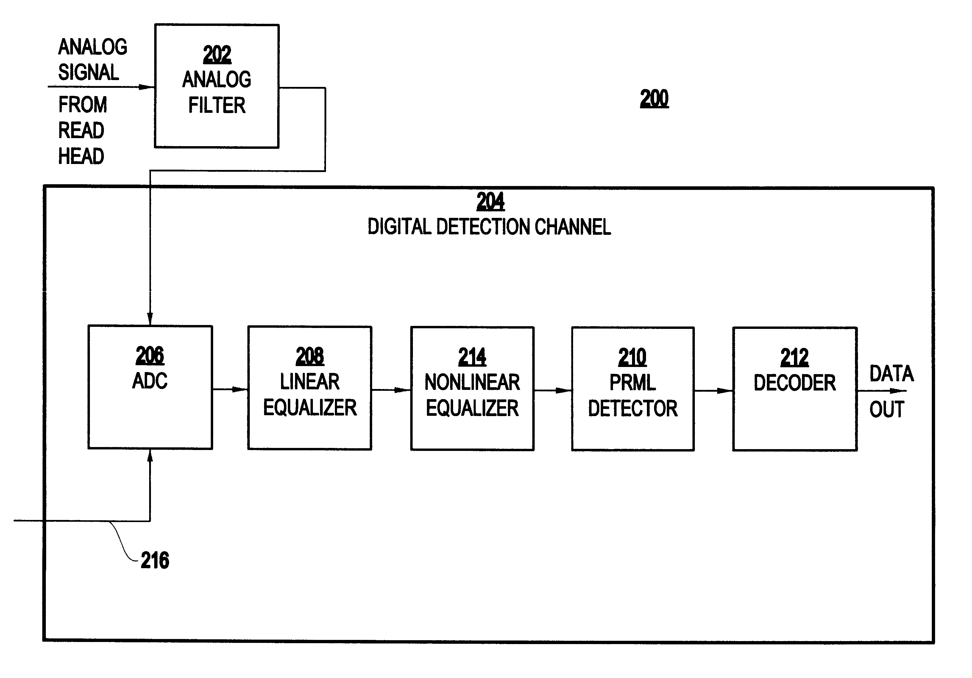
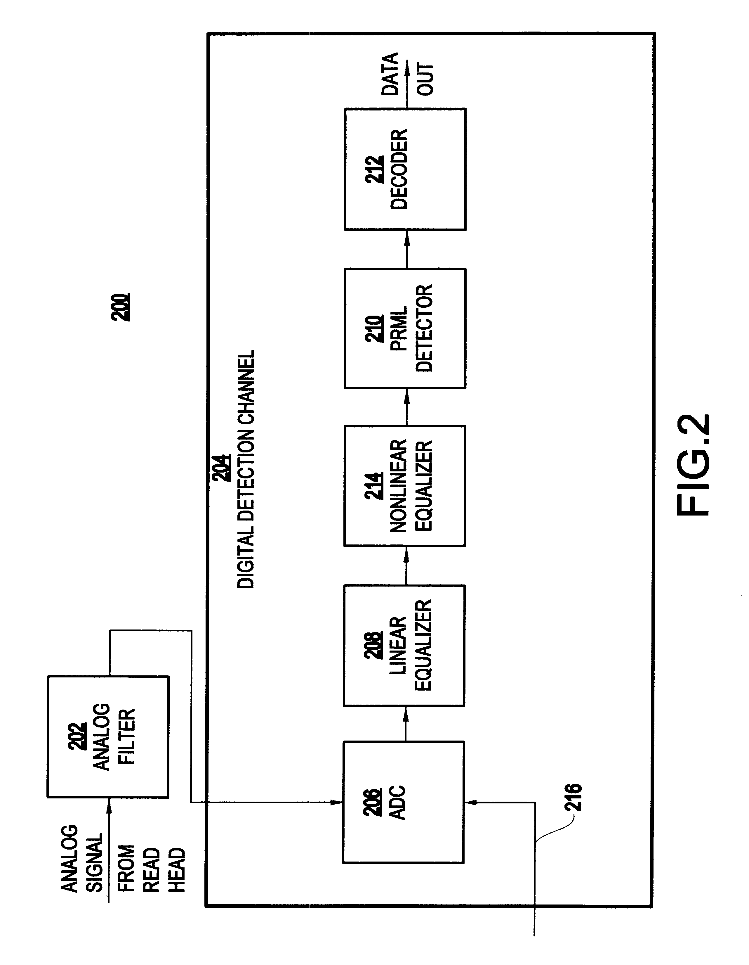
Referring now to the drawings, FIG. 2 is a block diagram showing a preferred embodiment of a data recovery circuit 200 according to the present invention.

As indicated in FIG. 2, in response to a read request, an analog signal from a read head is filtered by analog filter 202. The filtered analog signal is then applied to the digital detection channel 204 which includes an analog-to-digital converter (ADC) 206, linear equalizer 208, nonlinear equalizer 214, a partial response maximum likelihood (Viterbi) detector 210, and a decoder 212.

In the ADC 206, the filtered signal is sampled by clock 216. In conventional data recovery circuits, the analog-to-digital circuit typically samples the analog signal according to partial response, class IV metrics. However, in the inventive circuit 200, the ADC 206 samples the analog signal according to "PR4 wide" (PR4W) metrics so as to output a partial response sampled signal having four nonzero samples.

The PR4W sampling metric was created by the in...


PUM

PropertyMeasurementUnit
phase relationsaaaaaaaaaa
densitiesaaaaaaaaaa
Densityaaaaaaaaaa

Abstract

A decoding circuit has a nonlinear equalizer which employs a signal conditioning algorithm for conditioning a partial response sampled signal to eliminate intersymbol interference. The inventive decoding circuit has an analog-to-digital converter for sampling an analog signal, a linear equalizer for adjusting the amplitude and phase relations of the sampled signal, a nonlinear equalizer for conditioning the sampled signal and outputting a partial response sampled signal having two nonzero samples, and a partial response maximum likelihood detector, for detecting the partial response sampled signal having two nonzero samples.

Description

1. Field of the InventionThe present invention relates to a nonlinear equalizer and a decoding circuit and method using the same and, more particularly to a circuit and method having a nonlinear equalizer to eliminate intersymbol interference (ISI) in high density recording systems.2. Description of the Related ArtDigital magnetic recording systems typically experience severe nonlinearity at high densities. As explained by W. Zeng and J. Moon in "Systems Modeling of Nonlinear Effects in High Density Digital Magnetic Recording" (IEEE GLOBE.COM., Vol. 2, pp. 1139-1143, 1994), this nonlinearity is caused by the strong interactions between the adjacent written transitions. The demagnetization field of a written transition can cause the shift in position and broadening of the next transition. Adjacent transitions also tend to erase each other, causing significant reduction in the signal amplitude. Such nonlinear distortion is commonly referred to collectively as nonlinear intersymbol int...

Claims


Application Information

Patent Timeline
Patent Type & Authority Patents(United States)
IPC IPC(8): G11B20/10G11B5/09
CPCG11B5/09G11B20/10009G11B20/10037G11B20/10046G11B20/10055
Inventor MELAS, CONSTANTIN MICHAEL
Owner IBM CORP
Learn More