Cabinet structure for a magnetic tape recorder

a cabinet structure and magnetic tape recorder technology, applied in the field of cabinet structure for magnetic tape recorders, can solve the problems of noise signals that cannot reach the cylinder unit, and the distortion of reproduced pictures and sound

Inactive Publication Date: 2003-12-09
ORION ELECTRIC CO LTD
View PDF2 Cites 2 Cited by
  • Summary
  • Abstract
  • Description
  • Claims
  • Application Information

AI Technical Summary

Problems solved by technology

The cylinder unit installed in the deck of the magnetic tape recorder is very sensitive to such noise signals no matter how weak they may be in strength, causing a disturbance in reproduced pictures and sound.
In both of such conventional deck structures the cylinder unit is located so remote from the rear plate of the cabinet that noise signals can hardly reach the cylinder unit.

Method used


Image

  • Cabinet structure for a magnetic tape recorder
  • Cabinet structure for a magnetic tape recorder
  • Cabinet structure for a magnetic tape recorder

Examples


Embodiment Construction

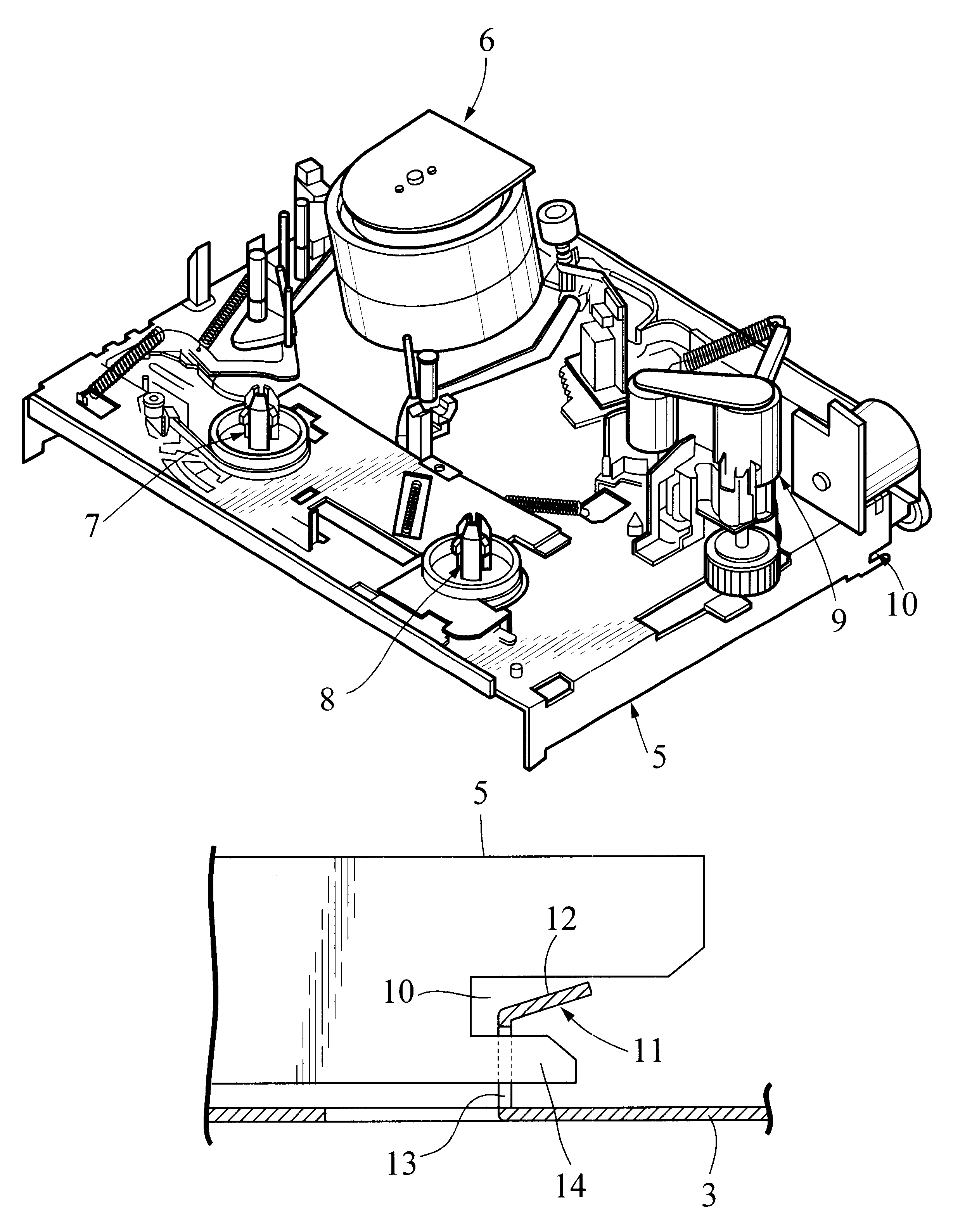
FIG. 1 shows a bottom frame 1 constituting a cabinet according to one preferred embodiment of the present invention and a deck of a magnetic tape recorder. The bottom frame 1 is made of a sheet of metal, comprising a bottom plate 3 and a rear or back plate 4, which is bolted or welded to the bottom plate 3. The bottom frame 1 may be made by stamping out from a sheet of metal and by bending the stamped metal sheet into a rear-and-bottom structure. The stamped bottom frame 1 has a resin plate or plates press-fitted in selected openings of its rear part, although not shown in the drawing.

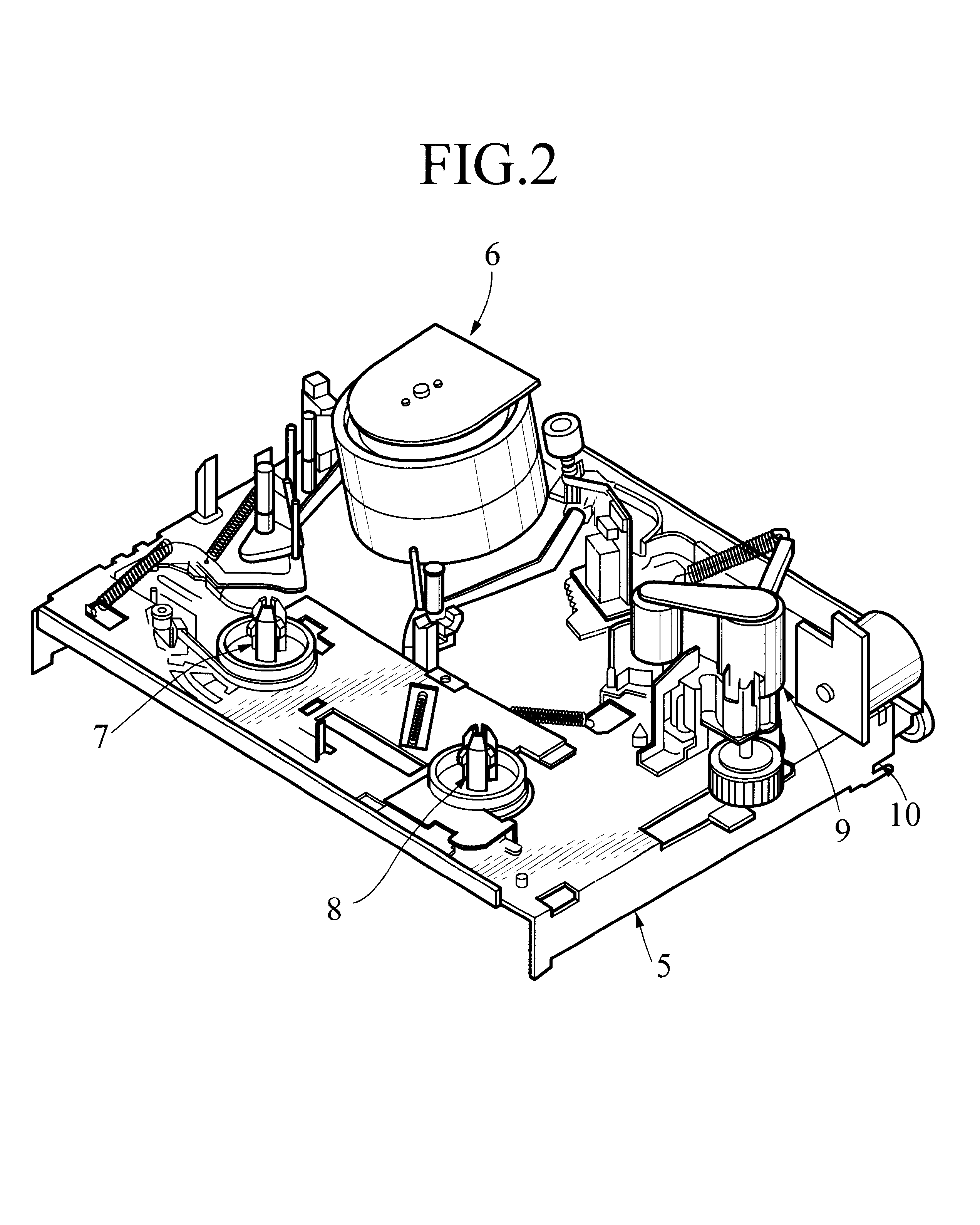
A base plate having a plurality of electronics mounted thereon (not shown) is fixed to the bottom part of the bottom frame 1. The base plate has posts standing upright therefrom, and the deck 2 is fixed to the bottom frame 1 via such posts. FIG. 2 shows one example of such deck 2. As shown in the drawing, a cylinder unit 6, reels 7 and 8, a pinch roll block 9 and other parts are mounted on the chassis ...


PUM

PropertyMeasurementUnit
shielding effectaaaaaaaaaa
frequencyaaaaaaaaaa
strengthaaaaaaaaaa

Abstract

Disclosed is a cabinet structure for a magnetic tape recorder having a rear-and-bottom structure to which a deck of the magnetic tape recorder is to be fixed. At least selected part or parts or the whole of the rear-and-bottom structure are of a sheet of metal capable of providing a shielding effect.

Description

1. Field of the InventionThe present invention relates to a cabinet structure for a magnetic tape recorder, and particularly to such a cabinet structure capable of providing a shielding effect.2. Related ArtsThe magnetic tape recorder is sensitive to exterior noise signals of high-frequency, such as electromagnetic wave produced by radio sets or hair dryers used in the vicinity of the magnetic tape recorder, allowing noise signals to appear in the pictures and sound reproduced on the screen. The cylinder unit installed in the deck of the magnetic tape recorder is very sensitive to such noise signals no matter how weak they may be in strength, causing a disturbance in reproduced pictures and sound.To prevent such a disturbance the cylinder unit is equipped with a shield plate. FIG. 4 shows a conventional deck structure having a cylinder unit and surrounding electronics and electric parts enclosed with a relatively large shield plate "a". FIG. 5 shows another conventional deck structu...

Claims


Application Information

Patent Timeline
Patent Type & Authority Patents(United States)
IPC IPC(8): G11B25/06G11B33/02G11B25/00G11B33/14
CPCG11B25/063G11B33/1493G11B33/02
Inventor SASAKI, KAZUO
Owner ORION ELECTRIC CO LTD
Why Eureka
Try Eureka