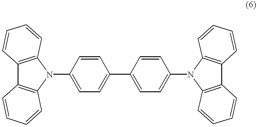
Organic electroluminescence element
a technology of electroluminescence element and organic material, which is applied in the direction of discharge tube luminescence screen, natural mineral layered products, transportation and packaging, etc., can solve the problems of low luminescence efficiency, low temperature, and inability to use temperature as a practical temperatur
- Summary
- Abstract
- Description
- Claims
- Application Information
AI Technical Summary
Problems solved by technology
Method used
Image
Examples
example 1
Production of an Organic EL Element
1 Washing
A glass substrate (made by Geomatic company) 25 mm in width, 75 mm in length and 1.1 mm in thickness, with ITO transparent electrodes, was subjected to ultrasonic washing in isopropyl alcohol for 5 minutes and subjected to UV ozone washing for 30 minutes.
2 Formation of a Hole Injection Layer
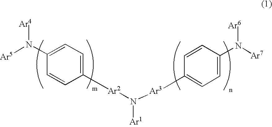
The washed glass substrate with the ITO transparent electrodes was set to a substrate holder in a vacuum evaporation device, and then N,N-bis(N,N-diphenyl-4-aminophenyl)-N,N-diphenyl-4,4'-diamino-1,1'-biphenyl (abbreviated to TPD232 hereinafter) was vapor-deposited on the substrate at a vacuum degree of 665.times.10.sup.-7 Pa and a vapor-deposition rate of 0.1 to 0.3 nm / sec., so as to form a first hole injection layer (which also had a function as a hole transport layer) having a thickness of 60 nm.
4,4-Bis[N-(1-naphtyl)-N-phenylamino]biphenyl (abbreviated to NPD hereinafter) was vapor-deposited on the TPD232 film at a vacuum degree of 665.times.10.sup.-...
example 2
An organic EL element was produced and evaluated in the same way as in Example 1 except that at the time of vapor-depositing BCP for the hole barrier layer in Example 1, metal Li, which is an alkali metal, and BCP were subjected to vapor co-deposition at a molar ratio of 1:1.
As a result, even by application of a DC voltage of 5 V, green luminescence having a luminescence brightness of 1,300 cd / m.sup.2 and a luminescence efficiency of 37 cd / A was obtained.
The organic EL element was driven at a low voltage. The initial brightness thereof was set to 500 cd / m.sup.2. In this way, a life span test was performed, so that the half-time was 700 hours.
A current-sending test as a heat-resistance test was performed at 85.degree. C. Even after current was sent for 200 hours, green luminescence having sufficient luminescence brightness was obtained.
example 3
An organic EL element was produced and evaluated in the same way as in Example 1 except that at the time of vapor-depositing BCP for the hole barrier layer in Example 1, metal Cs, which is an alkali metal, and BCP were subjected to vapor co-deposition at a molar ratio of 1:1.
As a result, even by application of a DC voltage of 4.5 V, green luminescence having a luminescence brightness of 1,200 cd / m.sup.2 and a luminescence efficiency of 40 cd / A was obtained.
The organic EL element was driven at a low voltage. The initial brightness thereof was set to 500 cd / m.sup.2. In this way, a life span test was performed, so that the half-time was 800 hours.
A current-sending test as a heat-resistance test was performed at 85.degree. C. Even after current was sent for 200 hours, green luminescence having sufficient luminescence brightness was obtained.
PUM
| Property | Measurement | Unit |
|---|---|---|
| glass-transition temperature | aaaaa | aaaaa |
| temperature | aaaaa | aaaaa |
| temperature | aaaaa | aaaaa |
Abstract
Description
Claims
Application Information
 - R&D
- Intellectual Property
- Life Sciences
- Materials
- Tech Scout
- Unparalleled Data Quality
- Higher Quality Content
- 60% Fewer Hallucinations
Browse by: Latest US Patents, China's latest patents, Technical Efficacy Thesaurus, Application Domain, Technology Topic, Popular Technical Reports.
© 2025 PatSnap. All rights reserved.Legal|Privacy policy|Modern Slavery Act Transparency Statement|Sitemap|About US| Contact US: help@patsnap.com


