Display apparatus
a display apparatus and display technology, applied in the direction of identification means, instruments, discharge tubes, etc., can solve the problems of crosstalk between these data lines, the display quality cannot be improved,
- Summary
- Abstract
- Description
- Claims
- Application Information
AI Technical Summary
Benefits of technology
Problems solved by technology
Method used
Image
Examples
first embodiment
[First Embodiment] (Overall construction of active-matrix substrate)
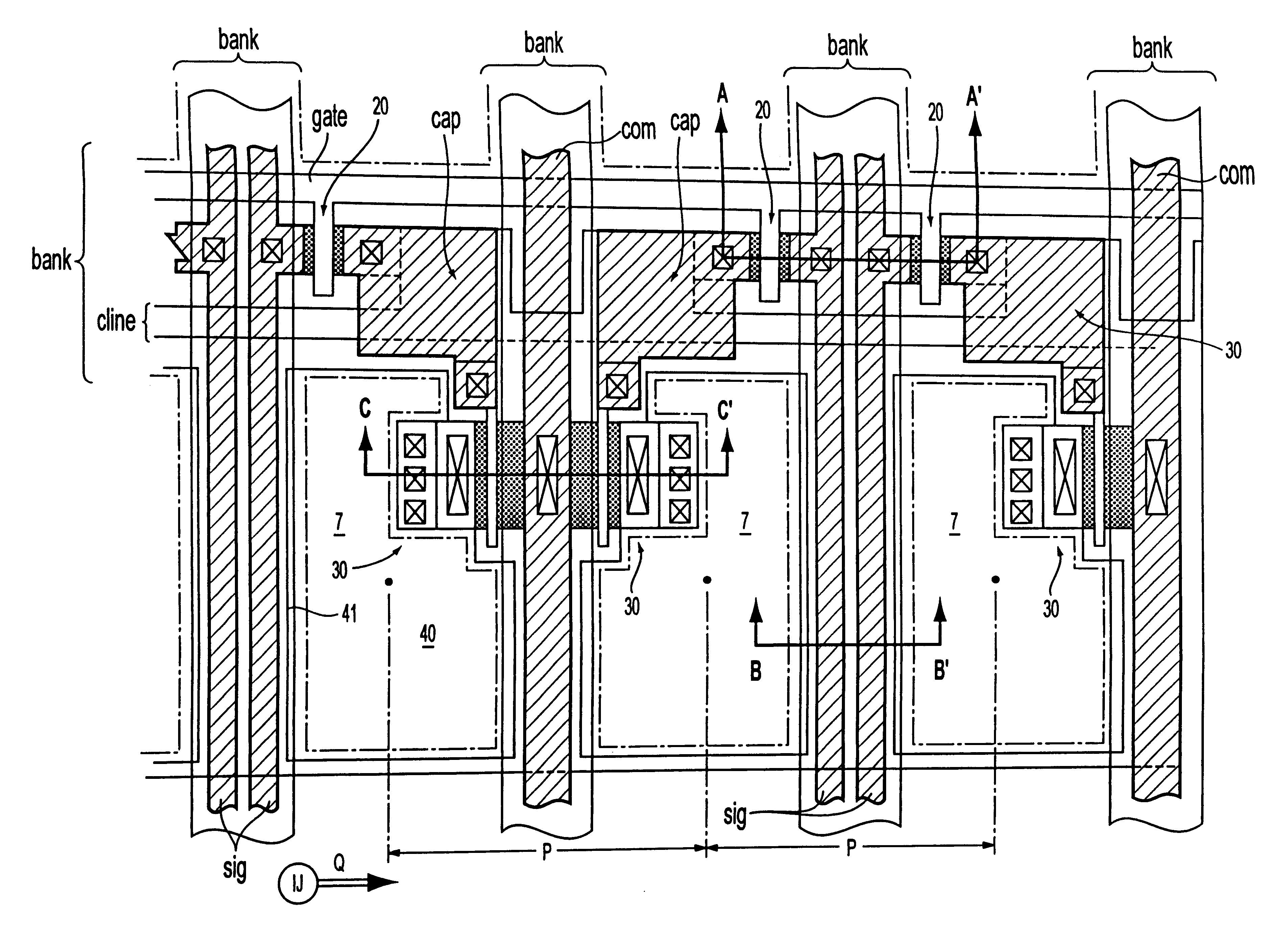
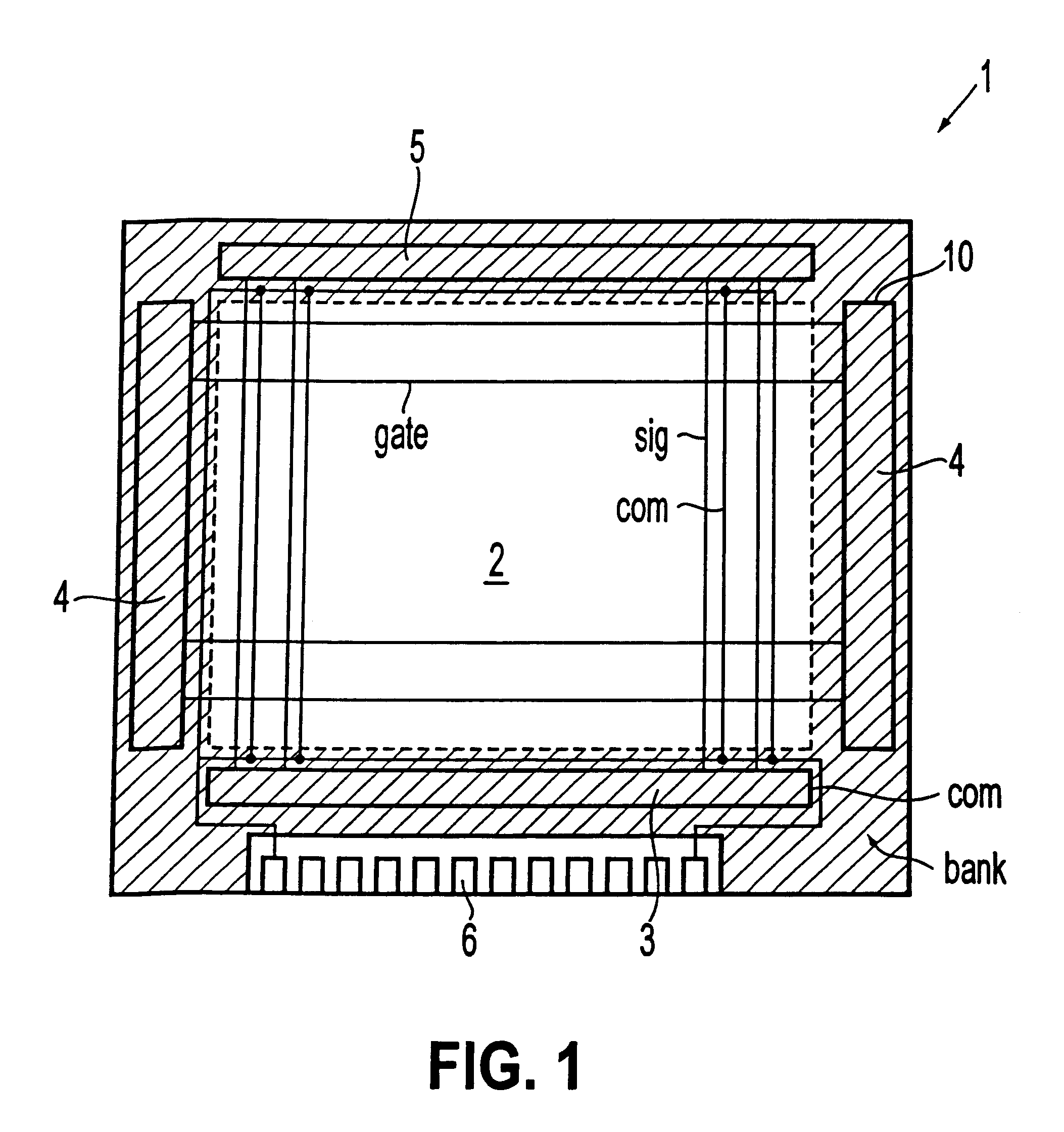
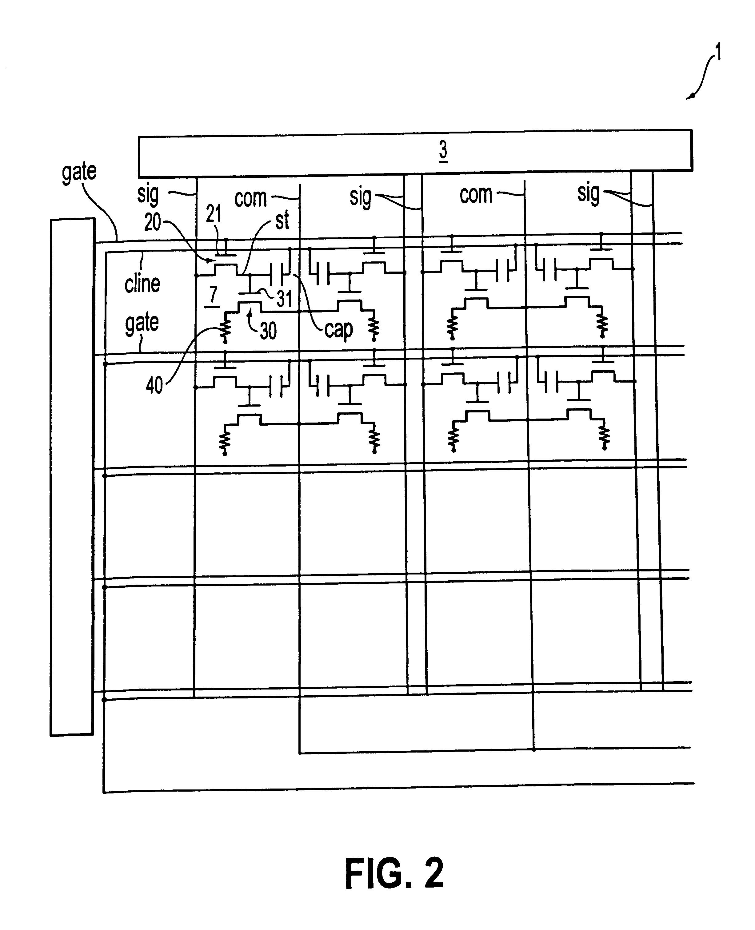
FIG. 1 is a block diagram schematically showing the overall layout of a display apparatus. FIG. 2 is an equivalent circuit diagram of an active matrix formed therein.
As shown in FIG. 1, in a display apparatus 1 of this embodiment, the central portion of a transparent substrate 10, which is a base body thereof, is formed into a display section 2. On both ends of the data lines "sig" of the peripheral portion of the transparent substrate 10, a data-side driving circuit 3 for outputting an image signal, and a checking circuit 5 are formed, and on both ends of the scanning lines "gate", a scanning-side driving circuit 4 for outputting a scanning signal is formed. In these driving circuits 3 and 4, a complementary TFT is formed by an n-type TFT and a p-type TFT. This complementary TFT forms a shift register, a level shifter, an analog switch, etc. On the transparent substrate 10, a mounting pad 6, which is a group of ter...
second embodiment
[Second Embodiment]
Although in the above-described first embodiment, the construction is formed in such a way that the light-emission elements 40 are driven by driving current of the same polarity in any pixel 7, as will be described below, the construction may be formed in such a way that the same number of two types of pixels 7, in which the light-emission elements 40 are driven by a driving current whose polarity is inverted, are among a plurality of pixels 7 to which driving current is passed in a section between the pixels and the same common power-feed line "com".
Examples of such constructions are described with reference to FIGS. 13 to 17. FIG. 13 is a block diagram of an embodiment in which two types of pixels, in which the light-emission elements 40 are driven by a driving current whose polarity is inverted, are structured. FIGS. 14 and 15 are each an illustration of a scanning signal, an image signal, the potential of common power-feed lines, and a potential of a potential...
third embodiment
[Third Embodiment]
From the viewpoint of the fact that pixels are arranged in such a way that driving current flows at an opposite polarity in a section between the pixels and the same common power-feed line "com", each pixel may be arranged as shown in FIG. 18. In this embodiment, since the construction of each of the pixels 7A and 7B is similar to that of the second embodiment. Therefore, the description has been omitted. In FIG. 18 and FIGS. 19 to 21, for describing each embodiment to be described below, a pixel corresponding to the pixel 7A described with reference to FIGS. 13, 14, and 16 is shown by the sign (-), and a pixel corresponding to the pixel 7B described with reference to FIGS. 13, 15, and 16 is shown by the sign (+).
As shown in FIG. 18, in this embodiment, the construction is formed in such a way that the polarity of the driving current in each of the pixels 7A and 7B is the same along the extension direction of the data lines "sigA" and "sigB" and that along the exte...
PUM
 Abstract
Description
Claims
Application Information
 - R&D
- Intellectual Property
- Life Sciences
- Materials
- Tech Scout
- Unparalleled Data Quality
- Higher Quality Content
- 60% Fewer Hallucinations
Browse by: Latest US Patents, China's latest patents, Technical Efficacy Thesaurus, Application Domain, Technology Topic, Popular Technical Reports.
© 2025 PatSnap. All rights reserved.Legal|Privacy policy|Modern Slavery Act Transparency Statement|Sitemap|About US| Contact US: help@patsnap.com


