
Electrical fan having an oil retaining ring to prevent loss and evaporation of lubricant oil

a technology of oil retaining ring and electric fan, which is applied in the direction of non-positive displacement fluid engine, pump components, piston pumps, etc., can solve problems such as noise or malfunction, and achieve the effect of reducing the evaporation or leakage of the oil retained in the fan and substantially increasing the longevity of the fan

Inactive Publication Date: 2003-09-02
IDEAL ELETHERMAL
View PDF25 Cites 27 Cited by
  • Summary
  • Abstract
  • Description
  • Claims
  • Application Information

AI Technical Summary

Benefits of technology

to provide an improved fan in which a stopper ring is mounted around a top of an oil-retaining bearing to buckle the oil-bearing bearing and stop a lubricant oil from leaking out. Thereby, evaporation or leakage of the oil retained in the fan can be favorably reduced, and the longevity of the fan can be substantially increased.
It is another object of the invention to provide an improved fan, in which a bottom of the shaft sleeve is provided with a wear resistant sheet, and optionally further provided with a magnet, and a magnetically susceptible sheet in order to prevent the oil contained in the oil-retaining bearing from leaking out.
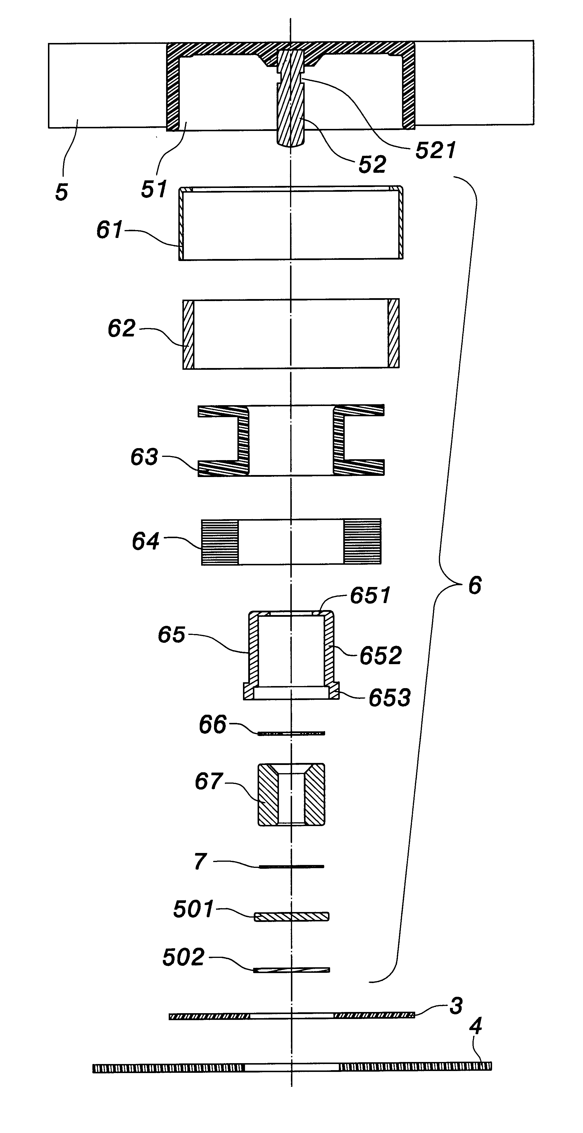
In accordance with the above and other objectives, the invention provides an improved fan that comprises a blade module and a coil module. The blade module includes a shaft and a recess. The recess defined in the blade module has a bottom where an end portion of the shaft is embedded. The coil module includes an oil-retaining bearing, an oil stopper ring and a shaft sleeve. The shaft sleeve has an internal flange at a top thereof. The oil-retaining bearing is mounted inside the shaft sleeve, and the oil-retaining ring is clamped between the internal flange and the oil-retaining bearing after the shaft of the blade module penetrates through the shaft sleeve and the oil-retaining ring. Via the oil stopper ring, the oil is retained in the oil-retaining bearing without substantial loss and evaporation. Thereby, the longevity of the fan of the invention is greatly increased.

Problems solved by technology

A substantial amount of heat is thus increasingly generated by friction, resulting in noise or malfunction.

Method used


Image

  • Electrical fan having an oil retaining ring to prevent loss and evaporation of lubricant oil
  • Electrical fan having an oil retaining ring to prevent loss and evaporation of lubricant oil
  • Electrical fan having an oil retaining ring to prevent loss and evaporation of lubricant oil

Examples


Embodiment Construction

Wherever possible in the following description, like reference numerals will refer to like elements and parts unless otherwise illustrated.

FIG. 4 and FIG. 5 show cross-sectional views of a fan according to an embodiment of the invention. The fan includes a blade module 5 and a coil module 6. The coil module 6 includes a shaft sleeve 65 having a bottom attached to a circuit board 3 and a base substrate 4.

A space 51 is defined through the blade module 5 to receive a shaft 52 at a central portion thereof. The space 51 has a bottom where an end portion of the shaft 52 is embedded. The coil module 6 includes a metallic case 61, a magnet 62, a frame 63 around which coils 64 are wound, the shaft sleeve 65, and an oil-retaining bearing 67. The metallic case 61 is mounted inside the space 51. The magnet 62 is placed inside the metallic case 61. The frame 63 is mounted inside the magnet 62 and generates a polarization change from positive to negative and reciprocally. The shaft sleeve 65 is m...


PUM


Abstract

An electrical fan comprising a blade module and a coil module. The blade module includes a space defined therein, and a shaft. The space has a bottom where an end portion of the shaft is embedded. The coil module includes an oil-retaining bearing, an oil-retaining ring, and a shaft sleeve. The shaft sleeve has an internal flange at a top thereof. The oil-retaining bearing is mounted inside the shaft sleeve, and the oil-retaining ring is clamped between the internal flange and the oil-retaining bearing once the shaft of the blade module has penetrated through the shaft sleeve and the oil-retaining ring of the coil module. Via the oil-retaining ring, the lubricant oil is retained in the oil-retaining bearing, thereby preventing loss and evaporation of lubricant oil.

Description

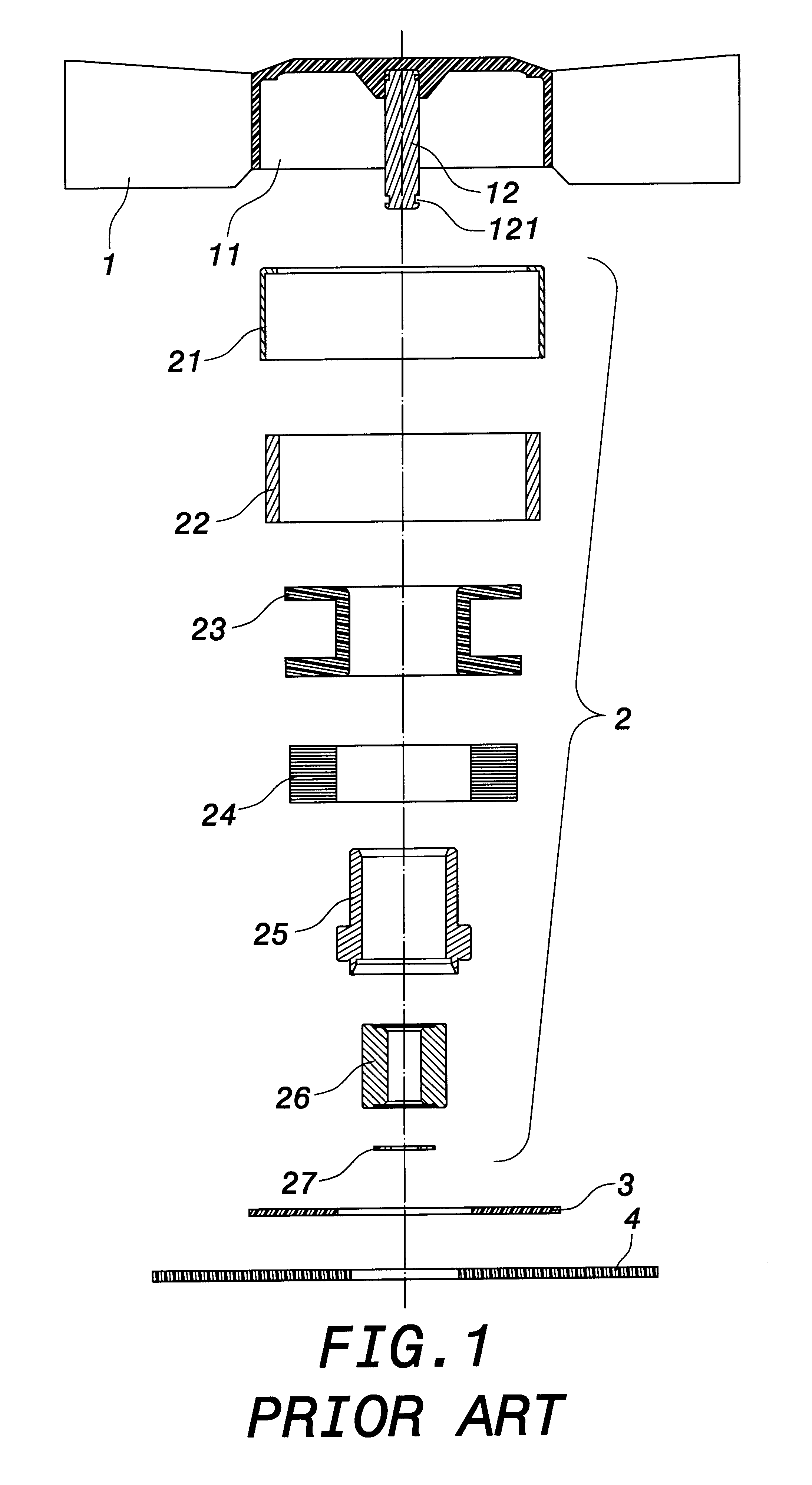
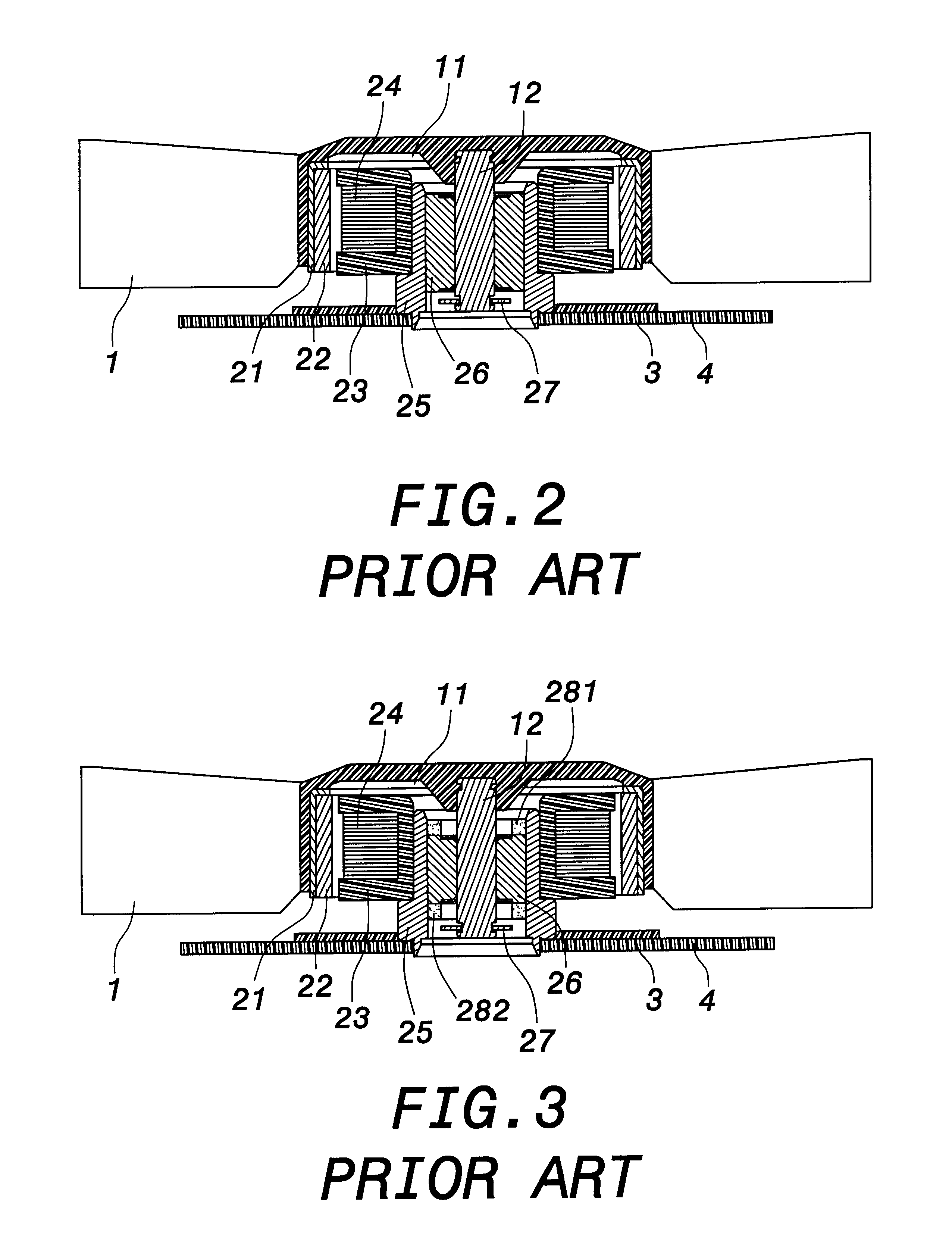
1. Field of the InventionThe invention relates to an electrical fan. More particularly, the invention relates to an electrical fan in which lubricant oil loss is prevented. Thereby, evaporation of the oil retained in the fan can be greatly reduced, and the longevity of the fan can be substantially increased.2. Description of the Related ArtOne type of conventional fans is shown in FIG. 1 and FIG. 2. In FIG. 1 and FIG. 2, the conventional fan mainly consists of a blade module 1, a coil module 2, a circuit board 3, and a base substrate 4. A space 11 is usually defined in the blade module 1 for accommodating the coil module 2. A shaft 12 is mounted at a center of the space 11, and further penetrates through the coil module 2 being placed into the space 11. The shaft 12 and the blade module 1 are together driven in rotation by means of the polarization change of the coil module 2. The coil module 2 has a case 21 which size matches the space 11. A magnet 22, a frame 23 around which coils...

Claims


Application Information

Patent Timeline
Patent Type & Authority Patents(United States)
IPC IPC(8): F04D29/06F04D29/08F04D29/12
CPCF04D29/063F04D29/122
Inventor SHIH, PO-JENLU, TAI-YING
Owner IDEAL ELETHERMAL
Learn More