
Air duct

a technology of air ducts and air ducts, which is applied in the direction of building components, heating types, applications, etc., can solve the problems of high production costs, complex design and construction, and frequent noise in the air ducts of the vehicle occupants

Inactive Publication Date: 2003-08-19
VALEO KLIMASYST
View PDF15 Cites 16 Cited by
  • Summary
  • Abstract
  • Description
  • Claims
  • Application Information

AI Technical Summary

Benefits of technology

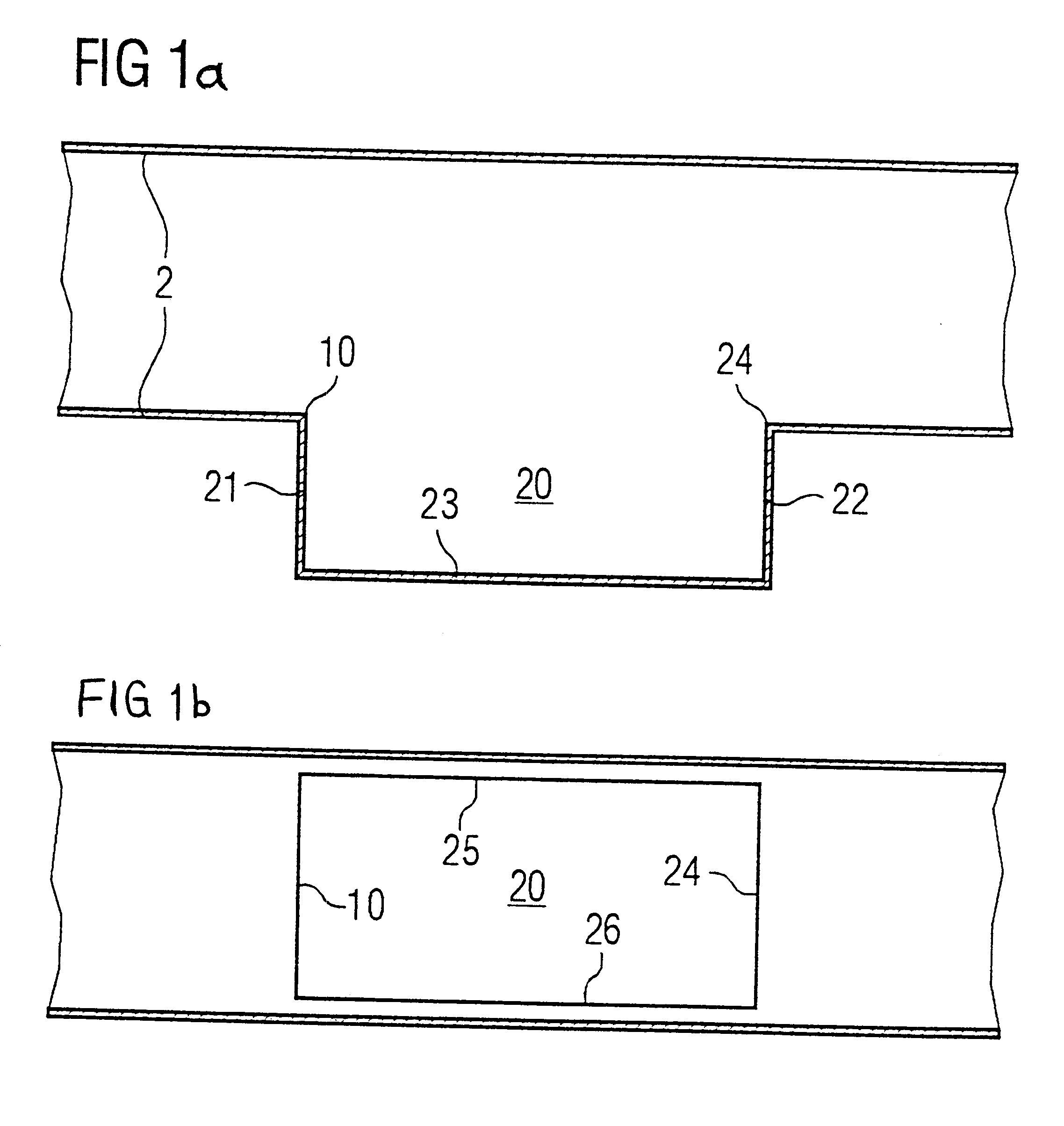
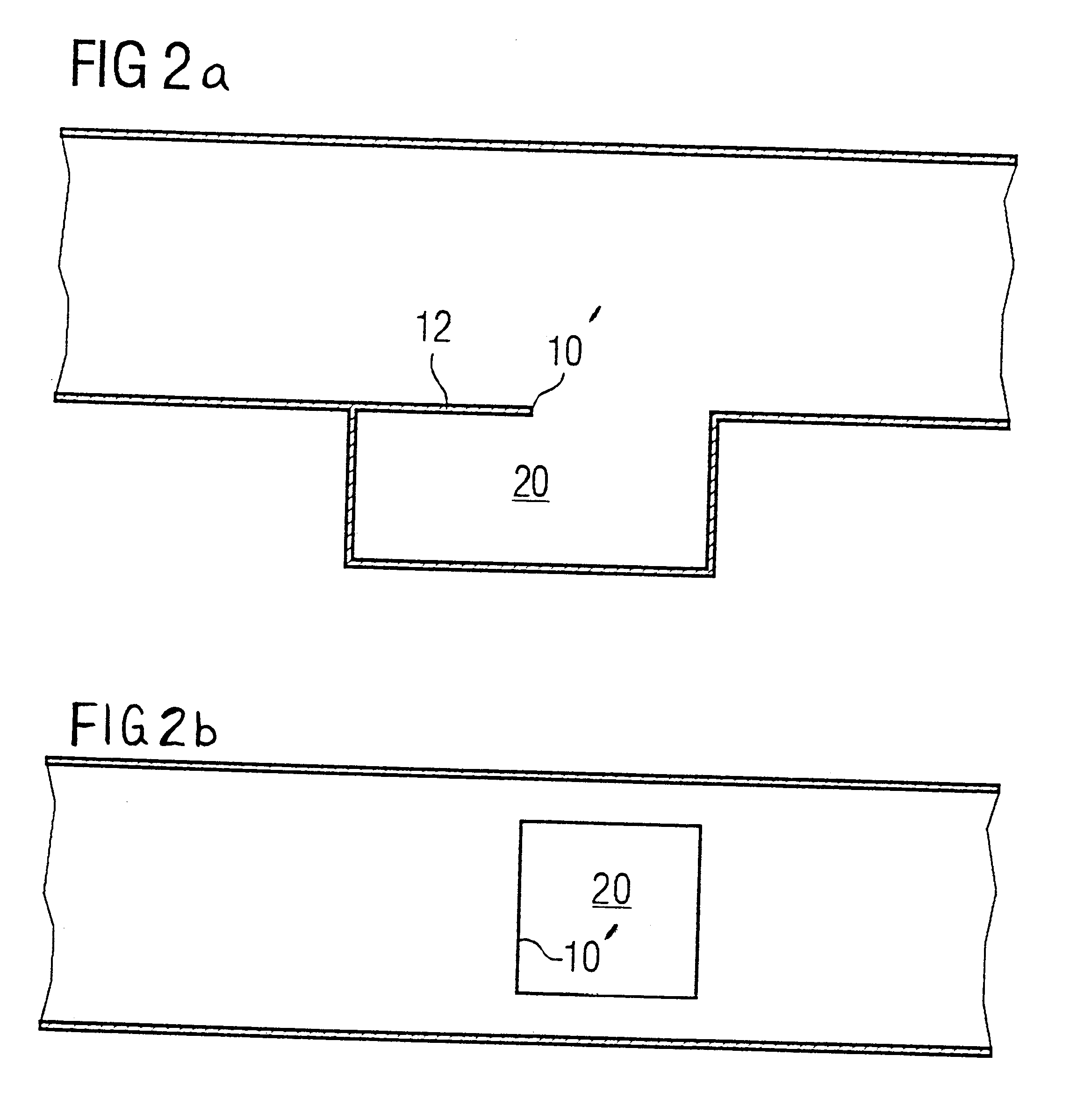
According to the invention, this object is achieved by virtue of the fact that at least one cross-sectional discontinuity is constructed in the case of a known air duct. Specifically, it has been shown surprisingly that contrary to the previous attempts to provide duct walls that are as continuous and smooth as possible, the construction of a cross-sectional discontinuity can contribute to reducing the development of noise and to damping already existing sound waves over a wide band by making use of phenomena which occur as purely acoustic scattering processes at the cross-sectional discontinuity. The cross-sectional discontinuity should extend substantially perpendicular to the flow direction in the air duct. In the case of particularly simple embodiments, the cross-sectional discontinuity is therefore provided substantially perpendicular to the air duct, although more complex shapes which take account of the flow profile in the air duct are also possible such as, for example, a parabolic shape. Different air duct geometries can therefore lead to different cross-sectional discontinuities.
Finally, it is preferred that a plurality of cross-sectional discontinuities are provided which are of different width, of different construction and / or with bordering cavities which are differently dimensioned / constructed. It is thereby possible to avoid the sound components, particularly in the medium frequency band from 1000 Hz to 5000 Hz, since the incoming sound waves of medium to higher frequencies are scattered at the respective cross-sectional discontinuities. Various instances of interference and damping of higher modes can lower the sound pressure at the higher frequencies owing to the variability of the plurality of cross-sectional discontinuities and / or the bordering cavities.

Problems solved by technology

In addition to noises which originate from the drive device of the blower, the blower wheel itself, or even the vehicle engine, unpleasant noises frequently arise in the air ducts for the vehicle occupants, in particular when the air speed is high.
A further disadvantage of what are termed Helmholtz resonators is to be seen in that not only are the design and construction complex, but the production also involves substantial additional costs, since virtually closed cavities at duct walls cannot be provided easily by injection-moulding technology.

Method used


Image

  • Air duct
  • Air duct
  • Air duct

Examples


Embodiment Construction

FIG. 1a shows in the top part a diagrammatic sectional view of an air duct as a preferred embodiment of the present invention. The air duct has a duct wall 2, which can, for example, define a rectangular cross section. At the reference numeral 10, a cross-sectional discontinuity is provided by an edge which defines a cavity 20 in addition to the volume of the air duct. In the sectional view shown, the cavity 20 has a substantially rectangular shape which is defined by a side wall 21, which adjoins the edge 10, a bottom wall 23 and a wall 22 which brings the cross section back to the dimension of that obtained before the cross-sectional discontinuity. The transition between the wall 22 and the duct wall defines an edge 24. As may be seen in the diagrammatic illustration of FIG. 1, there is thus a symmetrical configuration which provides a corresponding reduction in noise independently of the flow direction. However, it is to be assumed below that air enters the air duct on the left-h...


PUM


Abstract

An air duct, in particular for a motor vehicle heating, ventilating and / or air conditioning system, which is acoustically optimized by virtue of the fact that at least one cross-sectional discontinuity is constructed by making use of a phenomena which occur as acoustic scattering processes at the cross-sectional discontinuity. The cross-sectional discontinuity should extend substantially perpendicular to the flow direction in the air duct.

Description

1. Field of the InventionThe present invention relates in general to an air duct and, in particular, to an air duct in a motor vehicle heating, ventilating and / or air conditioning system.2. Description of Related ArtAir ducts are widely applied in the motor vehicle industry, inter alia, in order, for example, to guide air driven by a blower through a heating, ventilating and / or air conditioning system and, subsequently, towards outlets, for example in the region of the dashboard of the vehicle. In addition to noises which originate from the drive device of the blower, the blower wheel itself, or even the vehicle engine, unpleasant noises frequently arise in the air ducts for the vehicle occupants, in particular when the air speed is high. So far, it has been assumed that a duct wall as smooth and continuous as possible is to be provided in order to avoid noises.Furthermore, use has been made from time to time of what are termed Helmholtz resonators, which render it possible to reduc...

Claims


Application Information

Patent Timeline
Patent Type & Authority Patents(United States)
IPC IPC(8): F16L55/02F16L55/033B60H1/00
CPCB60H1/00564F16L55/033B60H2001/006Y10S454/906
Inventor SCHAAKE, NORMAN
Owner VALEO KLIMASYST
Learn More