Emission control system for generator engine

a technology of emission control system and generator engine, which is applied in the direction of machines/engines, mechanical equipment, separation processes, etc., can solve the problems of insufficient attention to the challenges, the exhaust emission of the internal combustion engine, and the life-threatening situation that makes effective pollution control of the marine generator engine critical, so as to reduce the concentration of pollutants and resist overheating

Inactive Publication Date: 2003-08-12
ENVIROELEVATOR
View PDF22 Cites 6 Cited by
  • Summary
  • Abstract
  • Description
  • Claims
  • Application Information

AI Technical Summary

Benefits of technology

to provide an apparatus resistant to overheating that is capable of reducing the concentration of pollutants in the exhaust emissions of an internal combustion engine.
As shown in FIGS. 2 and 5, the manifold 12 has an exit opening through which the exhaust pipe 19 of the treatment chamber 12 extends outward and into the atmosphere. After the gaseous emission stream has passed through the substrate 30 it flows toward the exhaust pipe 19. Positioned immediately in front of the exhaust pipe 19 is a retention plate 36. The retention plate 36 is connected to the inner surface of the treatment chamber 11 and covers a substantial portion, but not all, of the opening defined by the exhaust pipe 19, as shown in FIG. 7. This retards the flow of the gaseous emission stream proximate the substrate 30 to ensure a complete chemical reaction and breakdown of pollutants within the substrate 30. Finally, the gaseous emission stream exits the system 10 through exhaust pipe 19 and enters the atmosphere with a greatly reduced concentration of pollutants than when it initially entered the system 10. A substantial portion of the carbon monoxide and hydrocarbons in the gaseous emissions entering the system 10 are converted into carbon dioxide, oxygen, water vapor, and free carbon. Applicant has found that a typical carbon monoxide concentration of 50,000 parts per million in the gaseous emissions of a marine generator engine not using the system 10 is significantly reduced to twenty-five parts per million when operated in conjunction with the system 10.

Problems solved by technology

It is well known that internal combustion engines produce an exhaust emission containing pollutants that are harmful to the environment.
Pollution control for marine electric generator engines presents a unique set of challenges that have not been sufficiently addressed by the prior art.
The collection of toxic pollutants such as carbon monoxide near swimmers, particularly children, presents a potentially life-threatening situation making effective pollution control of marine generator engines critical.
Emission control devices, such as the ones disclosed in U.S. Pat. Nos. 5,410,871 and 5,419,123 can get extremely hot during operation-over 300.degree. Fahrenheit which can lead to overheating and fire.

Method used


Image

  • Emission control system for generator engine
  • Emission control system for generator engine
  • Emission control system for generator engine

Examples


Embodiment Construction

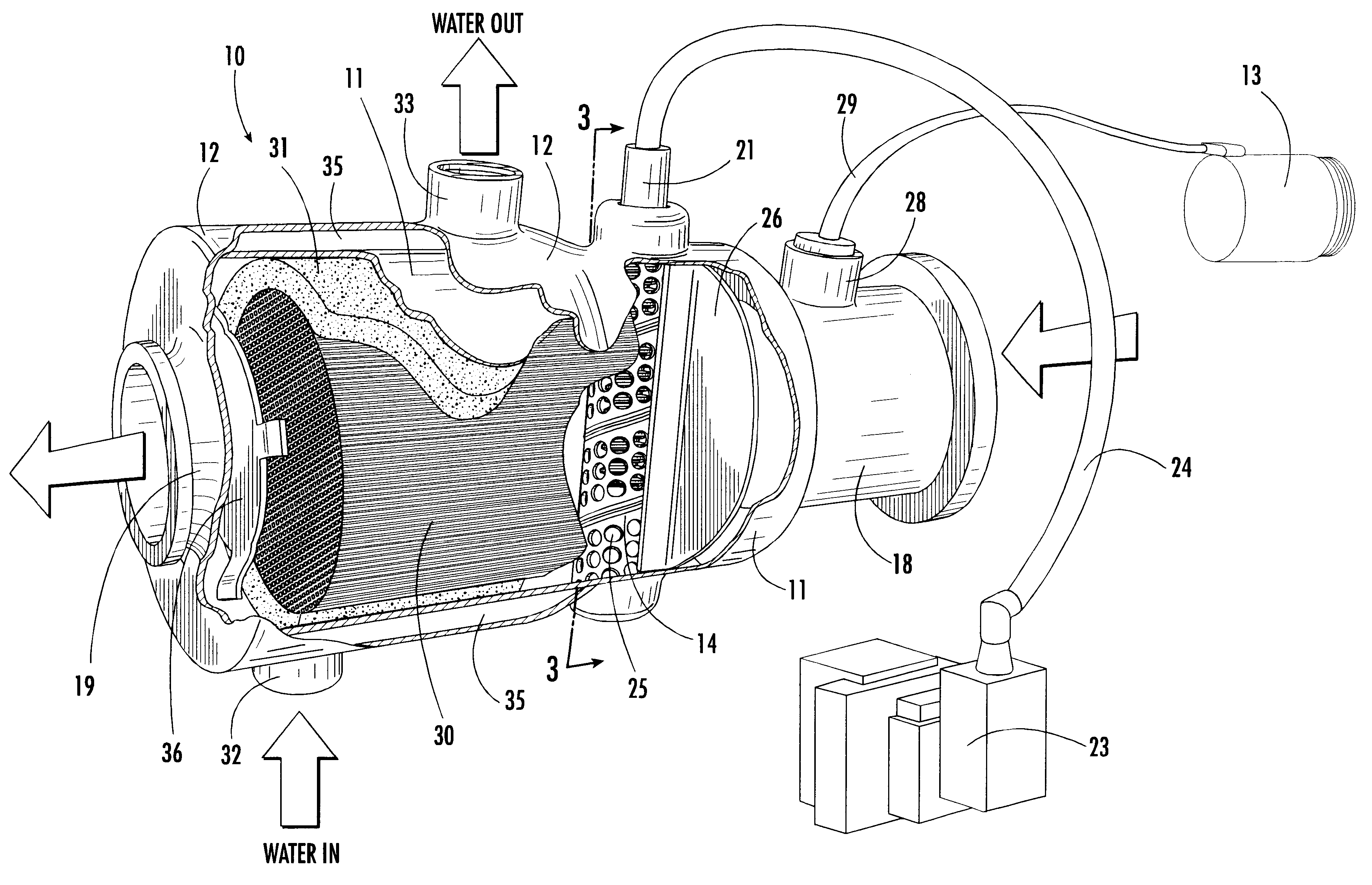
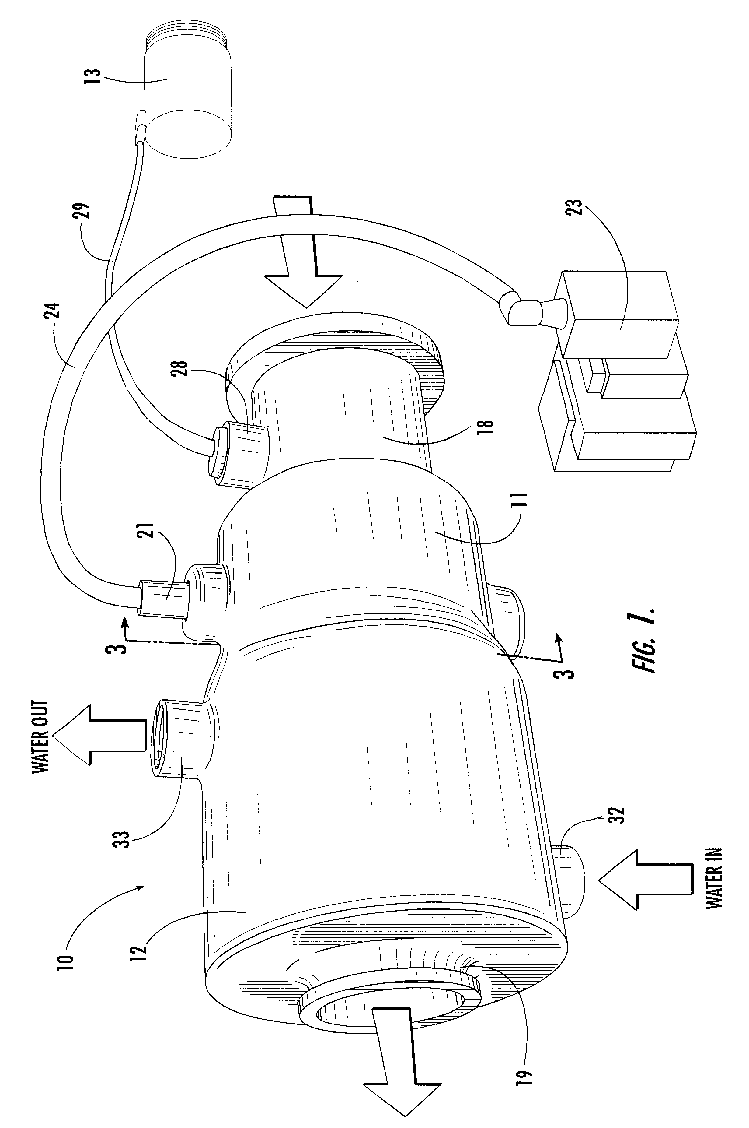
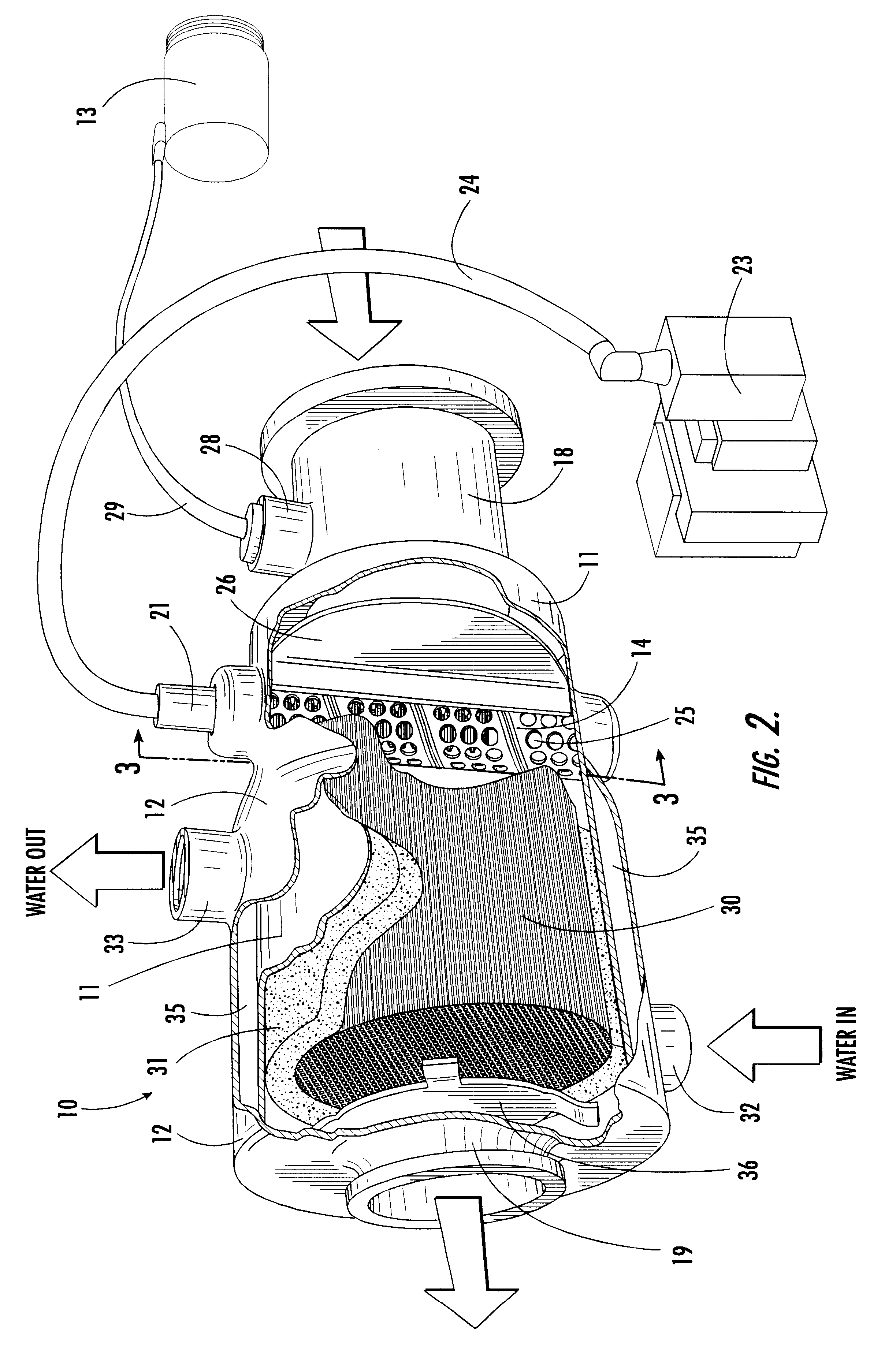
Referring now specifically to the drawings, a preferred embodiment of the emission control system according to the present invention is illustrated in FIG. 1, and shown generally at reference numeral 10. As can be seen in FIG. 2, the emission control system 10 comprises a treatment chamber 11 positioned within a manifold 12, and an air pump 13. A metal tube 14 containing an electrode 15, and a porous chemical substrate 16 are positioned within the treatment chamber 11 to promote a chemical reaction that reduces the concentration of pollutants in the gaseous emissions of a conventional marine electric generator engine 17, shown in FIG. 8.

As shown in FIG. 1, the treatment chamber 11 is a hollow cylinder, preferably made of 316 L stainless steel. The treatment chamber 11 includes an intake pipe 18 and an exhaust pipe 19 located at opposite lateral ends of the treatment chamber 11 that define openings through which a stream of gaseous emissions enters and exits the treatment chamber 11,...


PUM


Abstract

A system for reducing pollutants in internal combustion engine emissions, particularly marine electric generator engines, includes a treatment chamber having an intake opening for receiving gaseous emissions from the engine, and an exhaust opening for exiting emissions. A perforated metal tube is disposed within the treatment chamber, and an electrode is disposed within the metal tube in spaced apart relation to the metal tube. The electrode is encircled by the metal tube so that, upon applying a voltage at a predetermined frequency to the electrode, an arc is generated across the space between the electrode and the metal tube to promote a chemical reaction reducing the concentration of pollutants. The treatment chamber is contained within a manifold, and cooled by a flow of water. A supplemental air source is connected to the treatment chamber, and a chemical substrate is disposed within the treatment chamber for promoting the chemical reaction.

Description

TECHNICAL FIELD AND BACKGROUND OF THE INVENTIONThe invention relates to an apparatus for reducing the concentration of pollutants in the exhaust emissions of an internal combustion engine, particularly an engine driving an electric generator on a boat. The invention is particularly adapted for connecting to the exhaust manifold of a marine electric generator engine.It is well known that internal combustion engines produce an exhaust emission containing pollutants that are harmful to the environment. Such pollutants include carbon monoxide, carbon dioxide and various hydrocarbons. There are many inventions for reducing the concentration of such pollutants in engine exhaust emissions. For example, U.S. Pat. Nos. 5,410,871 and 5,419,123 each disclose emission control devices particularly suited for reducing pollutant levels in automobile exhaust emissions.Pollution control for marine electric generator engines presents a unique set of challenges that have not been sufficiently addresse...

Claims


Application Information

Patent Timeline
Patent Type & Authority Patents(United States)
IPC IPC(8): B01D53/32B01D53/92F01N3/28F01N3/08F01N3/05F01N7/00F01N3/30F01N13/00
CPCB01D53/323B01D53/92F01N3/05F01N3/08F01N3/0892F01N3/2828F01N3/2853F01N3/30F01N13/004F01N2590/02Y02T10/20Y02T10/12
Inventor MILLS, MICHAELJAMES, DAVID
Owner ENVIROELEVATOR
Why Eureka
Try Eureka