
Resonant chamber applicator for remote plasma source

a plasma source and applicator technology, applied in the field of remote plasma sources, can solve the problems of uneven water flow rate, localized hot spots in the body 31, and uneven arrangemen

Inactive Publication Date: 2003-08-05
APPLIED MATERIALS INC
View PDF7 Cites 245 Cited by
  • Summary
  • Abstract
  • Description
  • Claims
  • Application Information

AI Technical Summary

Benefits of technology

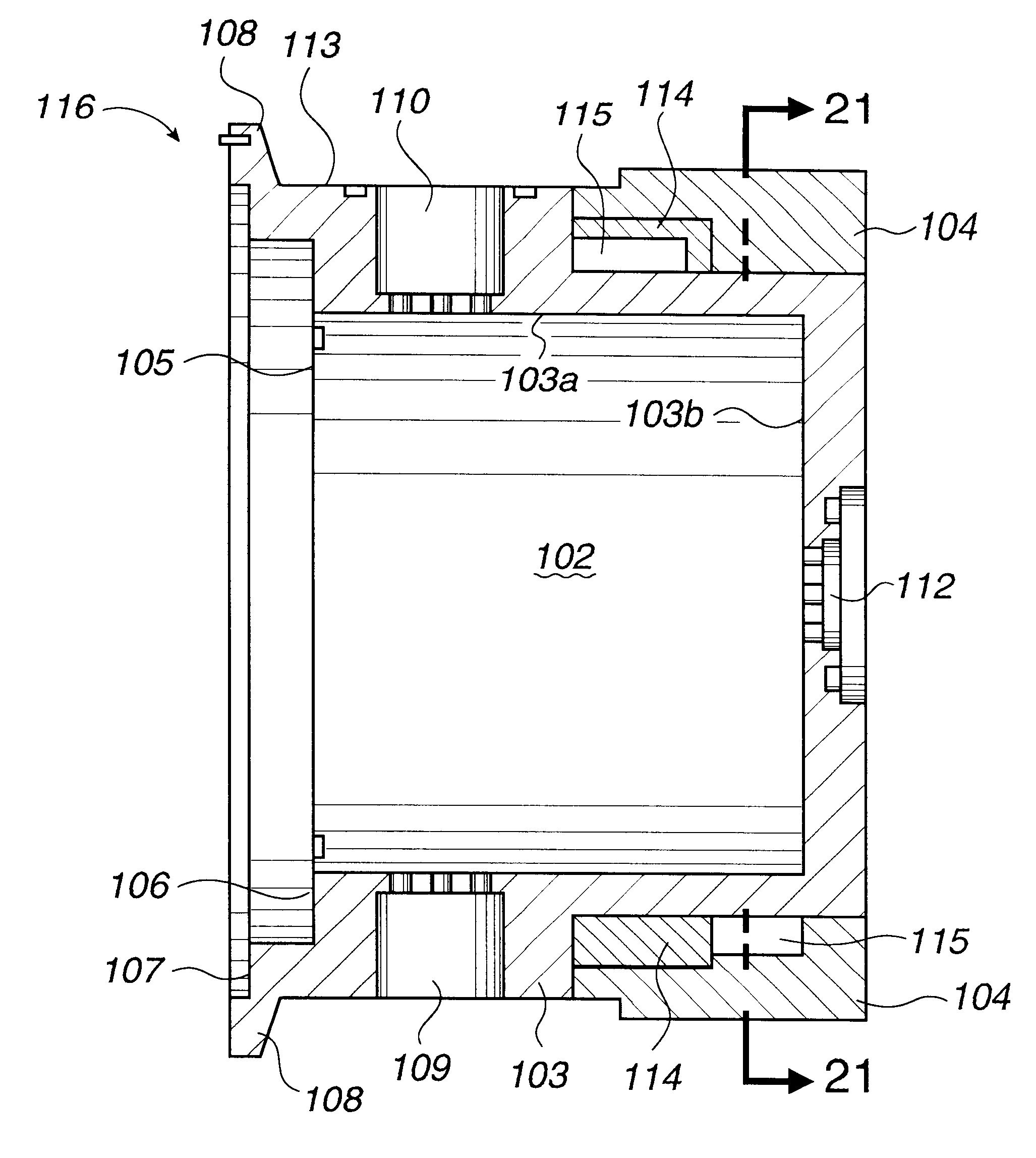
In the preferred embodiment, the cavity member 103 includes an interior, annular side wall portion 103a and a planar end wall portion 103b which define a generally cylindrically-shaped, resonant cavity 102 having a large front opening 105 through which the radial axis of the cylindrically-shaped cavity 102 extends. The end wall portion 103b contains a sensor port 112 which is comprised of a plurality of holes through which microwaves pass to the microwave sensor 131 (FIG. 7). The construction of the cavity member 103 as a single piece of metal in the preferred embodiment is advantageous over prior art plasma applicators, such as those of FIGS. 1 and 2, in that fewer pieces are used to enclose the resonant cavity 102. Thus fewer O-rings are required with a reduced likelihood of air leakage into the resonant cavity 102. Simpler assembly and reduced manufacturing costs may also be realized.
The tapered end 203c portion of the cavity member 203 provides increased surface area for the plate 226 to contact the cavity member 203. This results in a heat flow from the window 223 through the aperture plate 226 and to the cavity member 203 over a wider area. By providing a greater area through which the heat may flow, excessive localized hot spots are less likely to occur which decreases the possibility of heat damage to the plate 226 or the cavity member 203.

Problems solved by technology

This arrangement has some problems however.
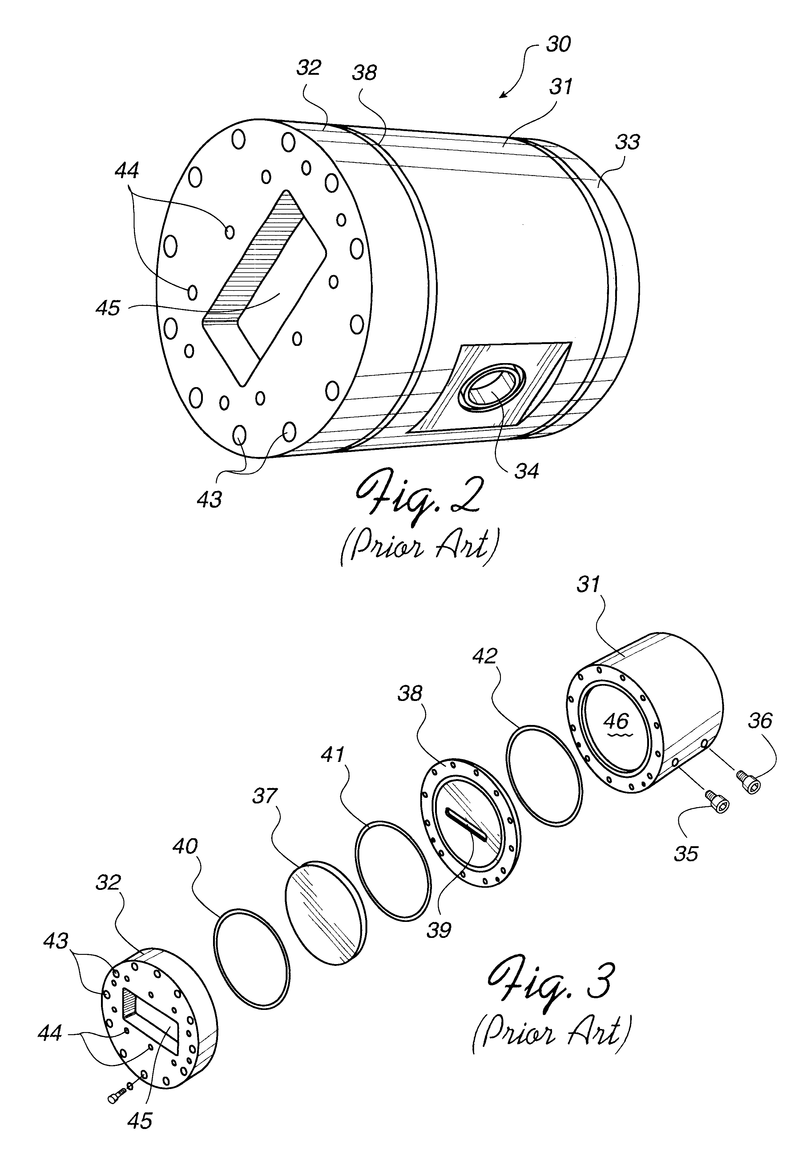
It is believed that this can result in uneven water flow rates and uneven heat removal rates which in turn can cause localized hot spots within the body 31.
While effective for its transparency to microwaves and impermeability to gases, aluminum nitride is a material which is typically relatively brittle and can crack or fracture relatively easily in the high temperature, operational environment of a microwave applicator.

Method used


Image

  • Resonant chamber applicator for remote plasma source
  • Resonant chamber applicator for remote plasma source
  • Resonant chamber applicator for remote plasma source

Examples


Embodiment Construction

A remote microwave plasma applicator of an improved design is provided. In one embodiment, the plasma applicator comprises a body having a cavity in which a plasma is generated from a gas. The body defines a coolant inlet port, a coolant outlet port and a coolant channel adapted to provide a series coolant flow path from the coolant inlet port to the coolant outlet port.

In one embodiment, the body is generally cylindrical in shape and the coolant channel provides a first flow path in fluid communication with a second flow path. The first flow path follows a generally circular path in a clockwise direction substantially around the circumference of the cylindrical body. The second flow path follows a generally circular path in a counter-clockwise direction substantially around the circumference of the cylindrical body.

In an alternative embodiment, the body has a proximate end opening adapted to admit microwave energy into the cavity and a distal end disposed generally on the opposite ...


PUM

PropertyMeasurementUnit
Lengthaaaaaaaaaa
Lengthaaaaaaaaaa
Flow rateaaaaaaaaaa

Abstract

An improved plasma applicator for remotely generating a plasma for use in semiconductor manufacturing is provided. In one embodiment, a plasma applicator is comprised of a chamber assembly, a removable waveguide adapter and a circular clamp which secures the adapter to the chamber assembly. The chamber assembly includes an aperture plate, a microwave transparent window, a chamber body and a microwave sensor which is mounted on the chamber body. The chamber body has a proximate end opening adapted to admit microwave energy into the cavity and a distal end disposed generally on the opposite side of the cavity from the proximate end opening. The chamber body further has a gas outlet port adapted to permit the flow of an excited gas out of the cavity and a gas inlet port adapted to admit a precursor gas into the cavity. The gas inlet port has a center axis which is disposed between the proximate end opening of the chamber body and the midpoint between the proximate end opening and the distal end of the body.

Description

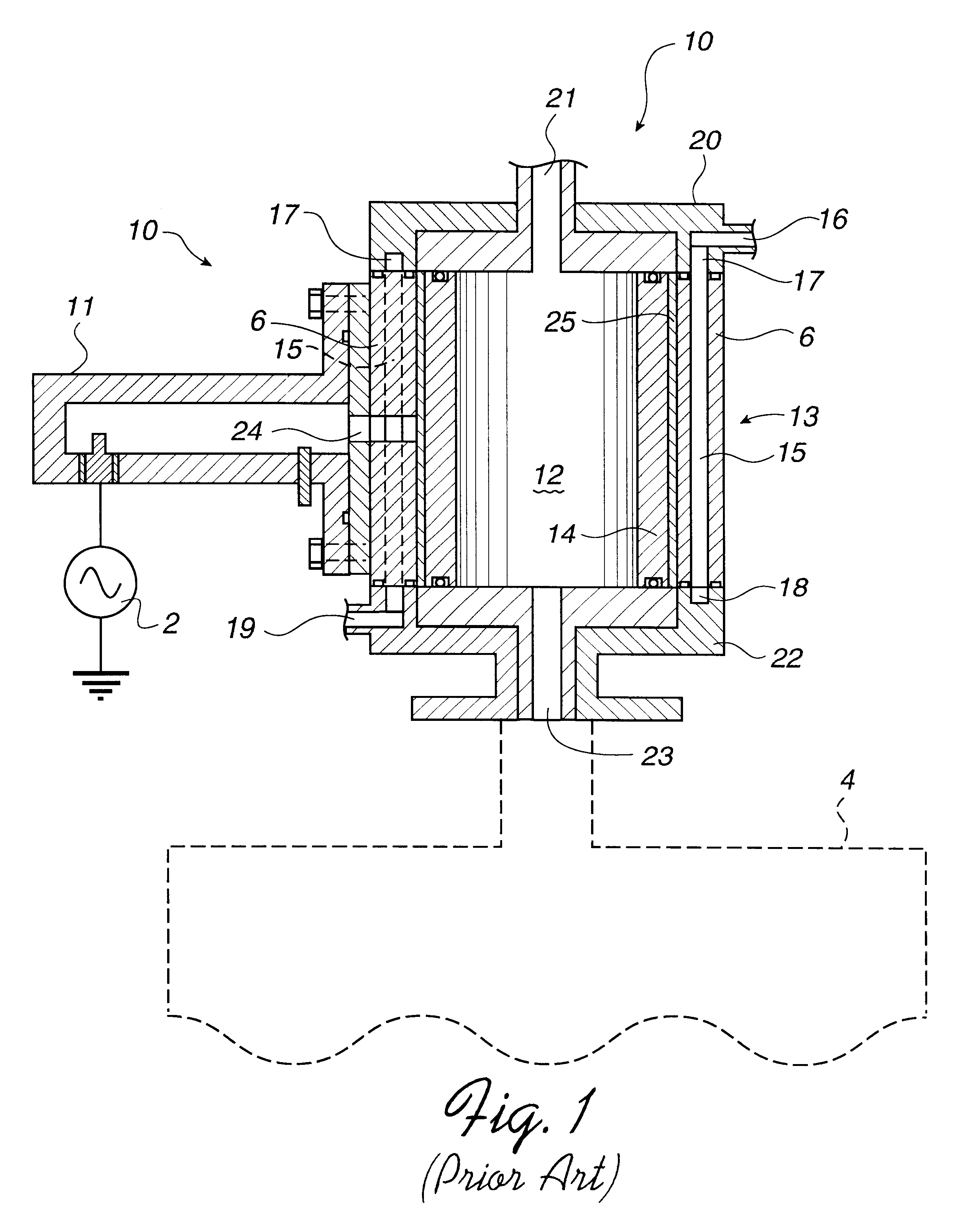
1. Field of the InventionThe present invention relates generally to a remote plasma source for exciting a process gas into a plasma state. More particularly, the present invention relates to a plasma applicator for delivering excited gas species into a processing chamber in which a substrate is to be processed.2. Description of the Related ArtPlasma processing is an important tool of the semiconductor manufacturing industry. This processing uses electromagnetic radiation to strike a plasma that produces a reactive species that is used for such process steps as wafer etching. A plasma may be produced directly above the surface of the wafer within the process environment, or the plasma may be remotely generated in an applicator, and then conducted to the surface of the wafer.FIG. 1 illustrates a known, remote plasma source 10 which can be used as a stand alone plasma source for cleaning, etching or depositing materials in a processing chamber 4 or in conjunction with other plasma sour...

Claims


Application Information

Patent Timeline
IPC IPC(8): H01J37/32
CPCH01J37/32192
Inventor VO, BE VANUMOTOY, SALVADOR P.TRINH, SON N.LEI, LAWRENCE CHUNG-LAIEDELSTEIN, SERGIOTEPMAN, AVIKAO, CHIEN-TEHTSAI, KENNETH
Owner APPLIED MATERIALS INC
Learn More