Dielectric leaky wave antenna having mono-layer structure
a leaky wave antenna and mono-layer technology, applied in leaky waveguide antennas, antennas, electrical equipment, etc., can solve the problems of increasing the manufacturing cost of through-hole processing, preventing the efficiency of the antenna to increase, and disadvantageously difficult to manufacture antennas using wave guides. achieve the effect of high efficiency
- Summary
- Abstract
- Description
- Claims
- Application Information
AI Technical Summary
Benefits of technology
Problems solved by technology
Method used
Image
Examples
first embodiment
(First Embodiment)
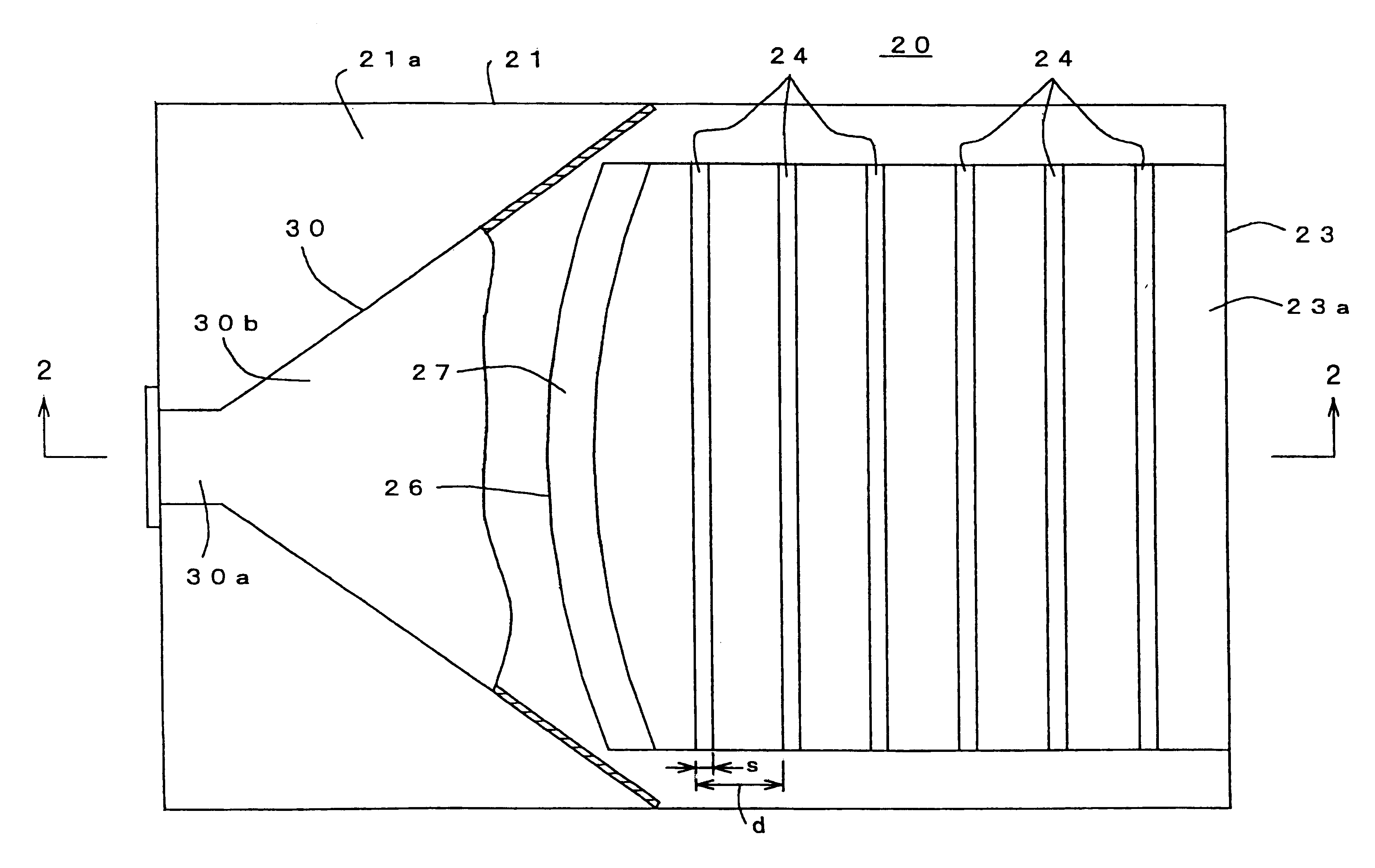
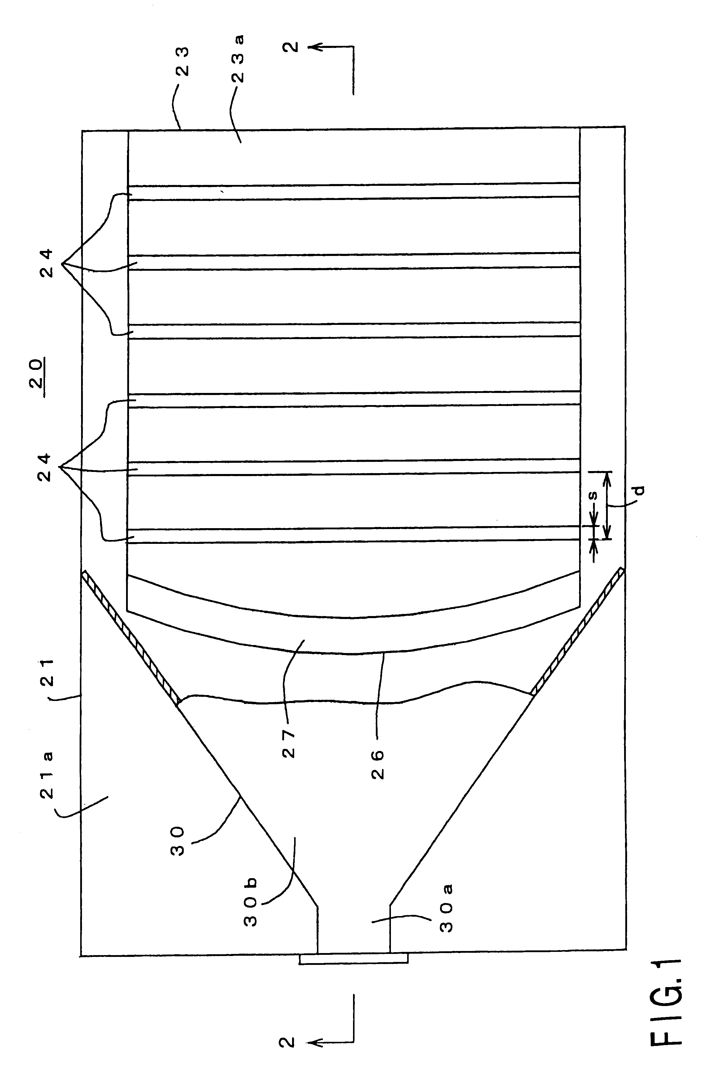
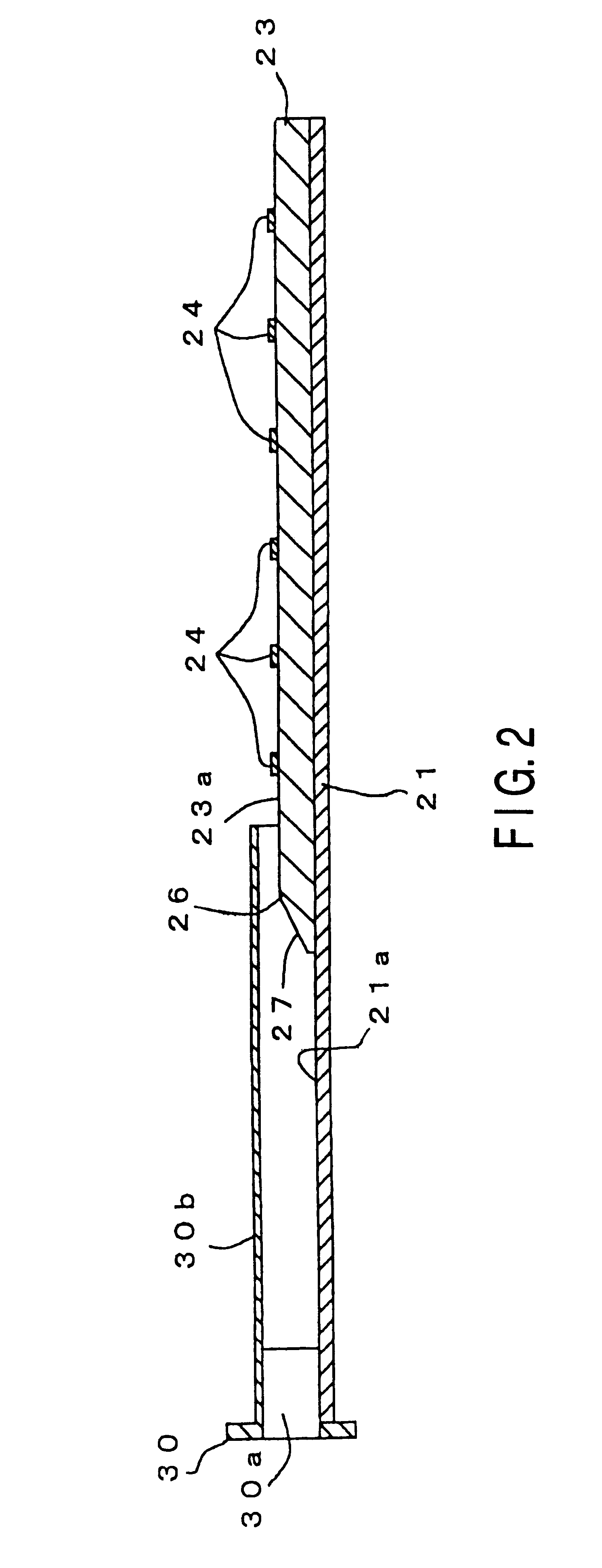
FIGS. 1 and 2 show a structure of a dielectric leaky-wave antenna 20 according to a first embodiment of the present invention.
This dielectric leaky-wave antenna 20 has a ground plane 21 consisting of a metallic flat plate.
A dielectric slab 23 forming a transmission guide for transmitting an electromagnetic wave between the dielectric slab 23 and the ground plane 21 is provided on a top surface 21a of the ground plane 21 in such a manner that a lower surface side of the dielectric slab 23 is laid on the ground plane 21.
This dielectric slab 23 consists of a dielectric material having a high dielectric constant for transmitting an electromagnetic wave, e.g., a substantially rectangular board which is made of alumina having a relative dielectric constant Er=9.7 and has a thickness of approximately 0.5 mm. One end side of the dielectric slab 23 is extended so as to curve.
Since the dielectric constant of the dielectric slab 23 is very large, the electromagnetic wave fed ...
second embodiment
(Second Embodiment)
On the contrary, a parabola reflecting type wave-front conversion section 46 may be used as in a dielectric leaky-wave antenna 40 according to a second embodiment shown in FIGS. 11 to 13.
FIGS. 11 to 13 show a structure of a dielectric leaky-wave antenna 40 according to the second embodiment of the present invention.
In the dielectric leaky-wave antenna 40 according to the second embodiment, the wave-front conversion section 46 has a reflecting wall 46a for reflecting the cylindrical wave and converting it into the plane wave and a guide section 46b for guiding the reflected planar wave to one end side of the dielectric slab 23'. The wave-front conversion section 46 is attached in such a manner that an upper half portion of the reflecting wall 46a is directed to one end side of the dielectric slab 23' and the aperture of the horn section 30b of the electromagnetic horn type feed 30 provided to the lower surface side of the ground plane 21 is closed by a lower half p...
third embodiment
(Third Embodiment)
FIG. 19 is a front view for illustrating a structure when the feed and the wave-front conversion section shown in FIG. 1 are modified as a dielectric leaky-wave antenna according to a third embodiment of the present invention.
For example, when modifying the above-described dielectric leaky-wave antenna 20 to a multi-beam radiation antenna, a bifocal type wave-front conversion section 26' (dielectric lens) is provided, and a feed 30' is constituted by a plurality of, e.g., five wave guide type radiators 51(1), 51(2), . . . 51(5) and a cover 52, as in a dielectric leaky-wave antenna 20' shown in FIG. 19.
Here, phase centers C1, C2, . . . , C5 of the respective radiators are arranged on the focal plane of the wave-front conversion section 26' or in the vicinity of the same.
In the dielectric leaky-wave antenna 20' having such a structure, as shown in FIG. 20, for example, the cylindrical wave Wa3 radiated from the central radiator 51(3) is converted as the plane wave Wb...
PUM
 Abstract
Description
Claims
Application Information
 - R&D
- Intellectual Property
- Life Sciences
- Materials
- Tech Scout
- Unparalleled Data Quality
- Higher Quality Content
- 60% Fewer Hallucinations
Browse by: Latest US Patents, China's latest patents, Technical Efficacy Thesaurus, Application Domain, Technology Topic, Popular Technical Reports.
© 2025 PatSnap. All rights reserved.Legal|Privacy policy|Modern Slavery Act Transparency Statement|Sitemap|About US| Contact US: help@patsnap.com


