
Method for treating photosensitive lithographic printing plate

Inactive Publication Date: 2003-05-06
AGFA NV
View PDF32 Cites 31 Cited by
  • Summary
  • Abstract
  • Description
  • Claims
  • Application Information

AI Technical Summary

Benefits of technology

Thus, an object of the present invention is to provide a method for treating a photosensitive lithographic printing plate, which gives a satisfactory image strength to an image obtained by laser light scanning exposure and development and reduces a required light exposure amount at the time of laser light exposure.
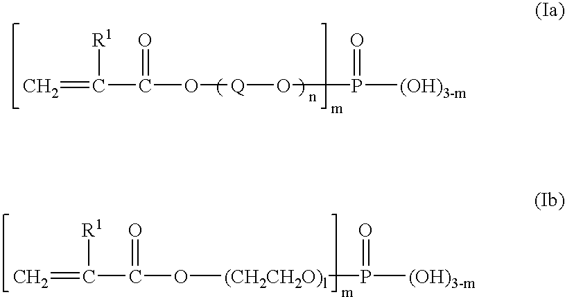
Further, preferable examples of an ethylenic compound include a phosphoric acid ester compound having at least one (meth)acryloyl group, and the aimed effect of the present invention can be satisfactorily achieved by using a photopolymerizable photosensitive composition containing said phosphoric ester compound in combination with an aluminum support anodized with an electrolyte containing sulfuric acid.

Problems solved by technology

However, since a photopolymer type photosensitive material is poor in adhesiveness with a support, there has been a problem that a printing resistance becomes extremely poor depending on plate making and printing conditions.
However, since this heat-treating step requires to maintain an apparatus at a high temperature, it is difficult to carry out unmanned operation even during night time and the apparatus must accompanied by an operator even after treatment until it is cooled to a certain level.
This makes an obstacle to the above-mentioned rationalization which is one of objects of CTP system.
However, according to the analysis by the present inventors, it has been found that even in the case of carrying out post-exposure, depending on a kind of photosensitive lithographic printing plate and a kind of a developer, a printing resistance and a developing property (stain property) before and after storing are unsatisfactory.
Also, in view of a general relation between a light intensity of a post-exposure light source and a distance from the light source to a surface to be exposed, the light intensity on the surface to be exposed was considered to be relatively low, usually at most about 15 mW / cm.sup.2, and such an image strength as to satisfy a commercial demand could not be achieved even by post-exposure treatment.

Method used


Image

  • Method for treating photosensitive lithographic printing plate
  • Method for treating photosensitive lithographic printing plate
  • Method for treating photosensitive lithographic printing plate

Examples


examples

Hereinafter, the present invention is more concretely explained by referring to the following Examples, but should not be limited thereto.

Preparation of High Molecular Binder-1

200 arts by weight of a copolymer of methyl methacrylate / isobutyl methacrylate / isobutyl acrylate / methacrylic acid=35 / 20 / 10 / 35 mol % (charge ratio) having a weight average molecular weight (Mw) of 70,000 (hereinafter referred to as "base resin-1"), 75 parts by weight of an unsaturated compound having the following cycloaliphatic epoxy group, 2.5 parts by weight of p-methoxyphenol, 8 parts by weight of tetrabutylammonium chloride, and 800 parts by weight of propylene glycol monomethyl ether acetate were placed in a reactor, and were reacted at 110.degree. C. for 24 hours in air with stirring to obtain a solution of high molecular binder-1 (acid value=60, an unsaturated group was reacted with 60% of the total methacrylic acid component of base resin-1). ##STR5##

Preparation of High Molecular Binder-2

855 Parts by w...


PUM


Abstract

A method for treating a photosensitive lithographic printing plate, which comprises exposing the photosensitive lithographic printing plate to laser light, developing with a developer containing an alkali metal silicate and then carrying out post-exposure treatment, said photosensitive lithographic printing plate being prepared by forming a photopolymerizable photosensitive layer having a film thickness of from 1.2 to 4 g / m2 and further forming a protective layer having a film thickness of from 2 to 8 g / m2 on a support having a centerline average height (Ra) of at least 0.35 mum.

Description

The present invention relates to a method for treating a photosensitive lithographic printing plate for exposure by laser.As used herein, mass amount per unit area, when described in connection with a coating, is described in terms of "thickness".PRIOR ARTSIn recent years, a printing plate making system (CTP system) which comprises outputting digital data inputted into a computer and edited, directly on a photosensitive lithographic printing plate by laser scanning lines, has been developed to be practically usable. By this step, a large rationalization of a printing plate making step has become possible. As a photosensitive lithographic printing plate used for this system, a photopolymer type photosensitive lithographic printing plate using a photopolymerizable photosensitive material is useful from viewpoints of easy handling, a problem of a waste water, and the like. However, since a photopolymer type photosensitive material is poor in adhesiveness with a support, there has been ...

Claims


Application Information

Patent Timeline
IPC IPC(8): B41C1/10G03F7/033G03F7/029G03F7/027
CPCB41C1/1008G03F7/027G03F7/029G03F7/033B41C1/1016Y10S430/146B41C2210/24Y10S430/165B41C2201/02B41C2201/14B41C2210/04B41C2210/06B41C2210/22Y10S430/145
Inventor TOSHIMITSU, ERIKOOKAMOTO, HIDEAKI
Owner AGFA NV
Learn More