
Transmitting circuit in which damage to power amplifier due to reflected wave is prevented and transmitter-receiver provided with the transmitting circuit

Inactive Publication Date: 2003-04-29
ALPS ALPINE CO LTD
View PDF8 Cites 20 Cited by
  • Summary
  • Abstract
  • Description
  • Claims
  • Application Information

AI Technical Summary

Benefits of technology

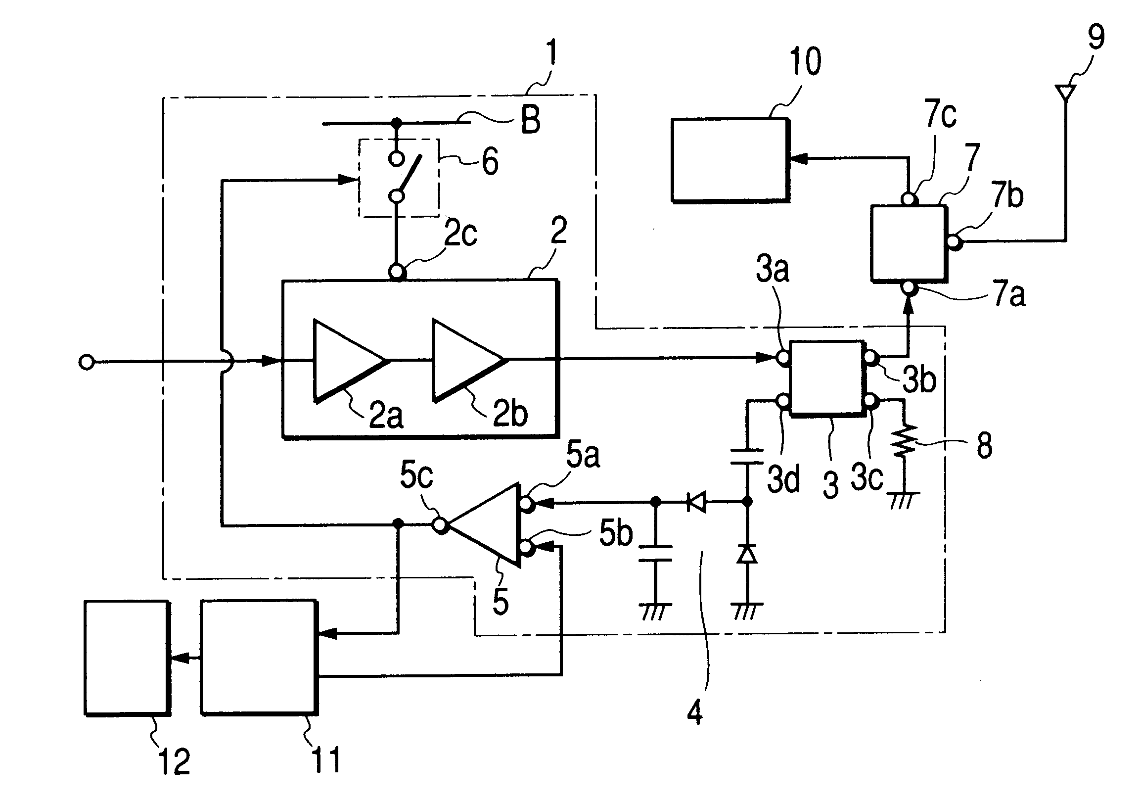
]As described above, a transmitting circuit according to the present invention has a power amplifier and a directional coupler provided between the power amplifier and an antenna, for detecting a reflected wave reflected from the antenna side on the power amplifier side in such a manner that when a level of the reflected wave exceeds a predetermined value, supply of power supply voltage applied to the power amplifier is cut off. Therefore, even if any reflected wave occurs due to an abnormal condition of the antenna, it is possible to prevent the power amplifier from being damaged without the aid of any expensive isolator.Also, a transmitting circuit according to the present invention has a power amplifier and a directional coupler provided between the power amplifier and the antenna, for detecting a reflected wave reflected from the antenna side on the power amplifier side in such a manner that when the level of the reflected wave exceeds the predetermined value, operating current flowing through an amplifier element of the power amplifier is reduced. Therefore, it is possible to prevent the power amplifier from being damaged due to the reflection similarly.In the transmitting circuit according to the present invention, the level of the predetermined value has been determined by rated power of the power amplifier and electric power to be transmitted by the power amplifier in such a manner that the power amplifier is not damaged by the reflected wave, and therefore, it is possible to reliably prevent the power amplifier from being damaged.The transmitting circuit according to the present invention has the directional coupler formed of a copper foil pattern on a circuit substrate, and therefore, the transmitting circuit can be further made lower in cost and smaller in size.The transmitter-receiver according to the present invention has the above-described transmitting circuit, the transmitting circuit has a duplexer between the power amplifier and the antenna, and there is provided the directional coupler between the power amplifier and the duplexer. Therefore, only the reflected wave can be detected by the directional coupler.In addition, since the transmitter-receiver according to the present invention has an indicator in such a manner that when the level of the reflected wave exceeds a predetermined value, the display screen of the indicator displays to the effect, it is possible for the user to confirm any abnormal condition of the antenna 7, and to exactly perform subsequent treatment such as repairing.

Problems solved by technology

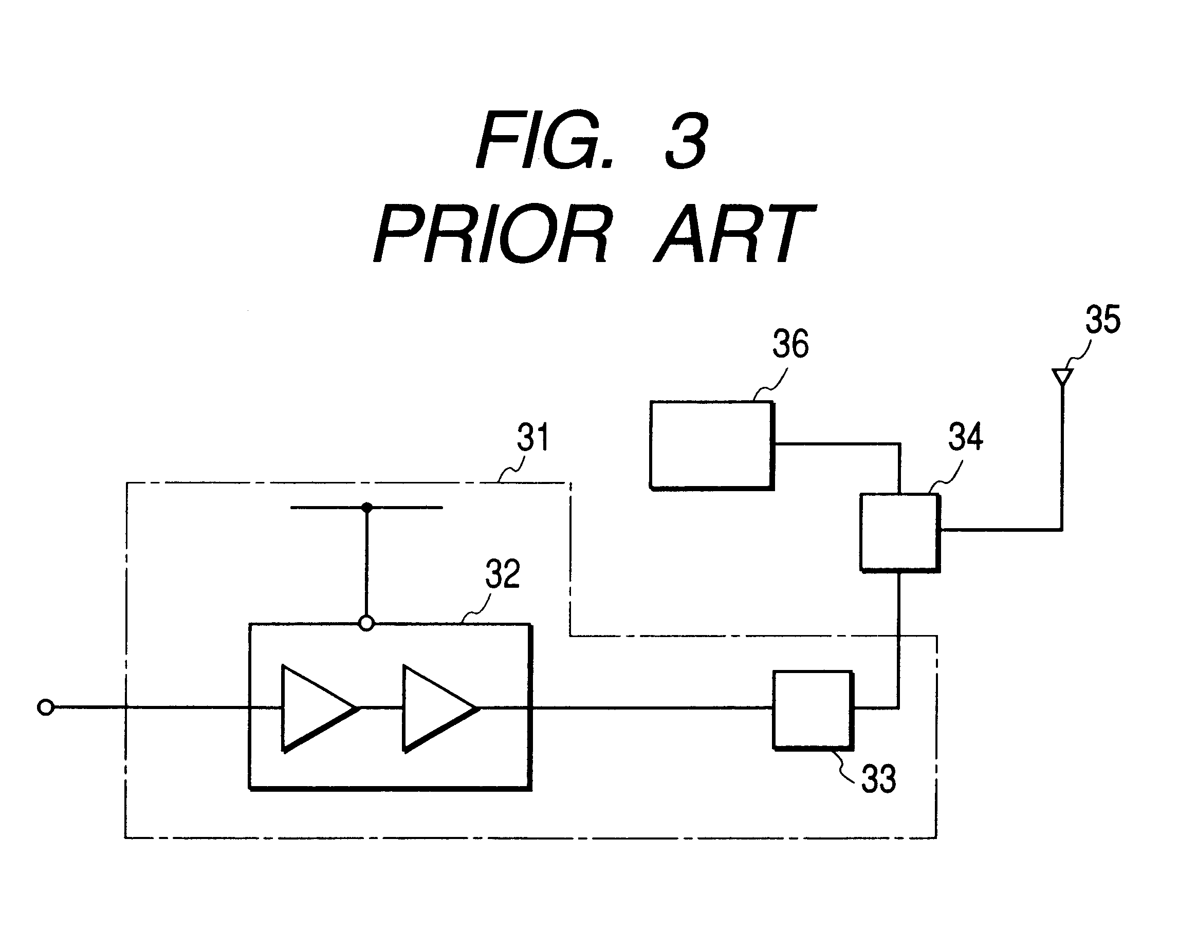
Therefore, the power amplifier 32 may possibly be damaged by a thermal runaway.
The isolator effectively functions as means to prevent the power amplifier from being damaged due to a reflected wave, but the first drawback is its high cost.

Method used


Image

  • Transmitting circuit in which damage to power amplifier due to reflected wave is prevented and transmitter-receiver provided with the transmitting circuit
  • Transmitting circuit in which damage to power amplifier due to reflected wave is prevented and transmitter-receiver provided with the transmitting circuit
  • Transmitting circuit in which damage to power amplifier due to reflected wave is prevented and transmitter-receiver provided with the transmitting circuit

Examples


first embodiment

FIG. 1 is a structural view showing a transmitting circuit and a transmitter-receiver according to the present invention. In FIG. 1, the transmitting circuit 1 has the power amplifier 2, the directional coupler 3, a voltage doubler detection circuit 4, a comparator 5, a switch 6 and the like. The power amplifier 2 is constructed in two stages by a first-stage amplifier 2a and a next-stage amplifier 2b, and a transmitting signal to be outputted from the next-stage amplifier 2b is inputted to the directional coupler 3 at the next stage. Inside the power amplifier 2, there is provided a bias circuit (not shown) for setting operating current which flows through an amplifying transistor. Further, the power amplifier 2 has a power supply end 2c to which supply voltage B is applied, and a control end 2d to which voltage for changing the operating current is applied. To the power supply end 2c, there is applied supply voltage B through a switch 6.

The directional coupler 3 has an input end 3...

second embodiment

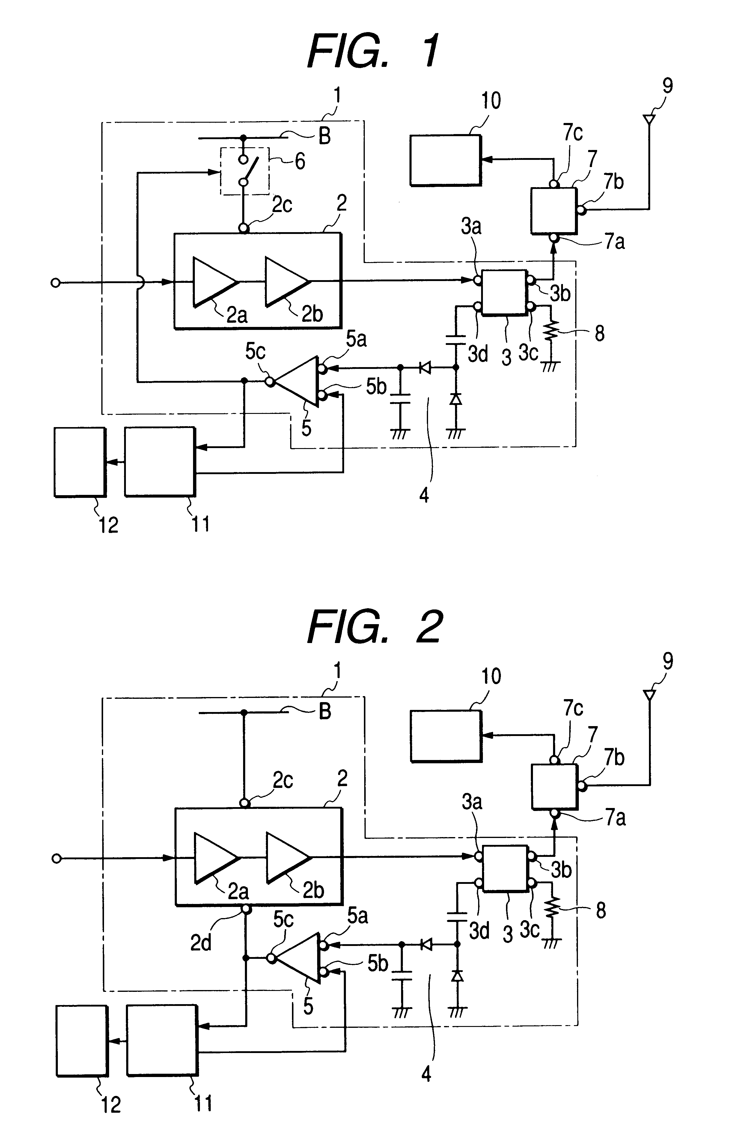
FIG. 2 is a structural view showing a transmitting circuit and a transmitter-receiver according to the present invention. In FIG. 2, the supply voltage B is directly applied to the power amplifier 2. An output end 5c of the comparator 5 is connected to a control end 2b of the power amplifier 2.

Operating current flowing through the power amplifier is arranged to decrease when voltage to be applied to the control end 2b drops. As a result, when the detection voltage obtained by detecting by the directional coupler 3 becomes higher than the reference voltage Er, the operating current flowing through the power amplifier 2 is reduced to decrease the power to be consumed, thus preventing any damage. The other structure is the same as that shown in FIG. 1.

[Effect of the Invention]

As described above, a transmitting circuit according to the present invention has a power amplifier and a directional coupler provided between the power amplifier and an antenna, for detecting a reflected wave ref...


PUM


Abstract

The power amplifier will be prevented from being damaged due to a reflected wave without the aid of any expensive isolator. There are disposed a power amplifier as well as a directional coupler provided between the power amplifier and an antenna, for detecting a reflected wave reflected from the antenna side on the power amplifier side in such a manner that when a level of the reflected wave exceeds a predetermined value, supply of power supply voltage applied to the power amplifier is cut off.

Description

1. Technical Field of the InventionThe present invention relates to a transmitting circuit for use in, for example, a portable telephone, and a transmitter-receiver provided with the transmitting circuit.2. Prior ArtFIG. 3 is a structural view showing a conventional transmitter-receiver, a transmitting circuit 31 has a power amplifier 32 and an isolator 33, and a transmitting signal is amplified by the power amplifier 32, and is outputted to an antenna 35 via the isolator 33 and a duplexer 34 sequentially.On the other hand, a receiving signal received by the antenna 35 is inputted to a receiving circuit 36 via the duplexer 34.In this case, if impedance between the power amplifier 32 and the antenna 35 is matched, all transmitting signals to be outputted from the power amplifier 32 will be transmitted to the antenna 35. If, however, for example, the antenna 35 is broken and is disconnected from the duplexer 34, the transmitting signals to be transmitted will be total-reflected to be ...

Claims


Application Information

Patent Timeline
IPC IPC(8): H04B1/04H04B1/3822H04B1/40
CPCH04B1/0466H04B1/04
Inventor SHIBAMURA, YOUSUKE
Owner ALPS ALPINE CO LTD
Learn More