
Method and apparatus for improved eye-hand co-ordination during videoscopic surgery

a technology of eye-hand coordination and videoscopic surgery, applied in the field of minimally invasive endoscopic surgery, can solve the problems of severe nausea, observer discomfort, and poor substitute for natural binocular vision, and achieve the effects of reducing discomfort, reducing pain, and reducing discomfor

Inactive Publication Date: 2003-04-15
STREET GRAHAM S B
View PDF4 Cites 8 Cited by
  • Summary
  • Abstract
  • Description
  • Claims
  • Application Information

AI Technical Summary

Benefits of technology

It is an object of the current invention to provide a vision system which enables an observer to relate to an object field through a three-dimensional image scaled in proportion to said object field, so as to provide an environment for comfortable eye-hand co-ordination. More specifically, the invention is intended to provide a generalised method for improving eye-hand co-ordination, during videoscopic surgery.
It is a further object of the invention to provide the three-dimensional image substantially free from binocular disparity between corresponding points which would not be observed were the object field to be viewed directly.
It is also an object of the invention to provide the observer with both left and right eye images simultaneously, in order to more effectively simulate the conditions of normal binocular viewing of an object field.
It is another object of the invention to minimise the conflict between accommodation and convergence by providing suitable viewing conditions for the observer.
Advantageously, in use, peak white within the image viewed has a luminance in excess of 200 candela per square metre, whereby dilation of the pupil of each of the observer's eyes is limited, the observer retains a good depth of field and conflict between accommodation and convergence for a stereoscopic image is mitigated and / or avoided.

Problems solved by technology

It has been accepted for some considerable time that a conventional two-dimensional (flat) image is a poor substitute for the natural binocular vision enjoyed by a surgeon, when carrying out an open surgical procedure.
Unfortunately, the handicap imposed on the surgeon's dexterity (eye-hand co-ordination) by the impaired vision provided through a conventional video image has been a brake on the migration of this technique to a variety of more complex procedures.
However, a variety of commercial attempts to address the problem, have met with poor acceptance by the surgical profession, and it has been the recognition of this reality that has provided the incentive to analyse why such first generation three-dimensional visualisation systems failed.
A substantial 3D effect would be observed, but, after some time, the observer would begin to feel uncomfortable and, in some cases, would suffer severe nausea.
In addition, the improvement in eye-hand co-ordination was not always as great as was expected.
Historically there have been a number of factors which have created problems.
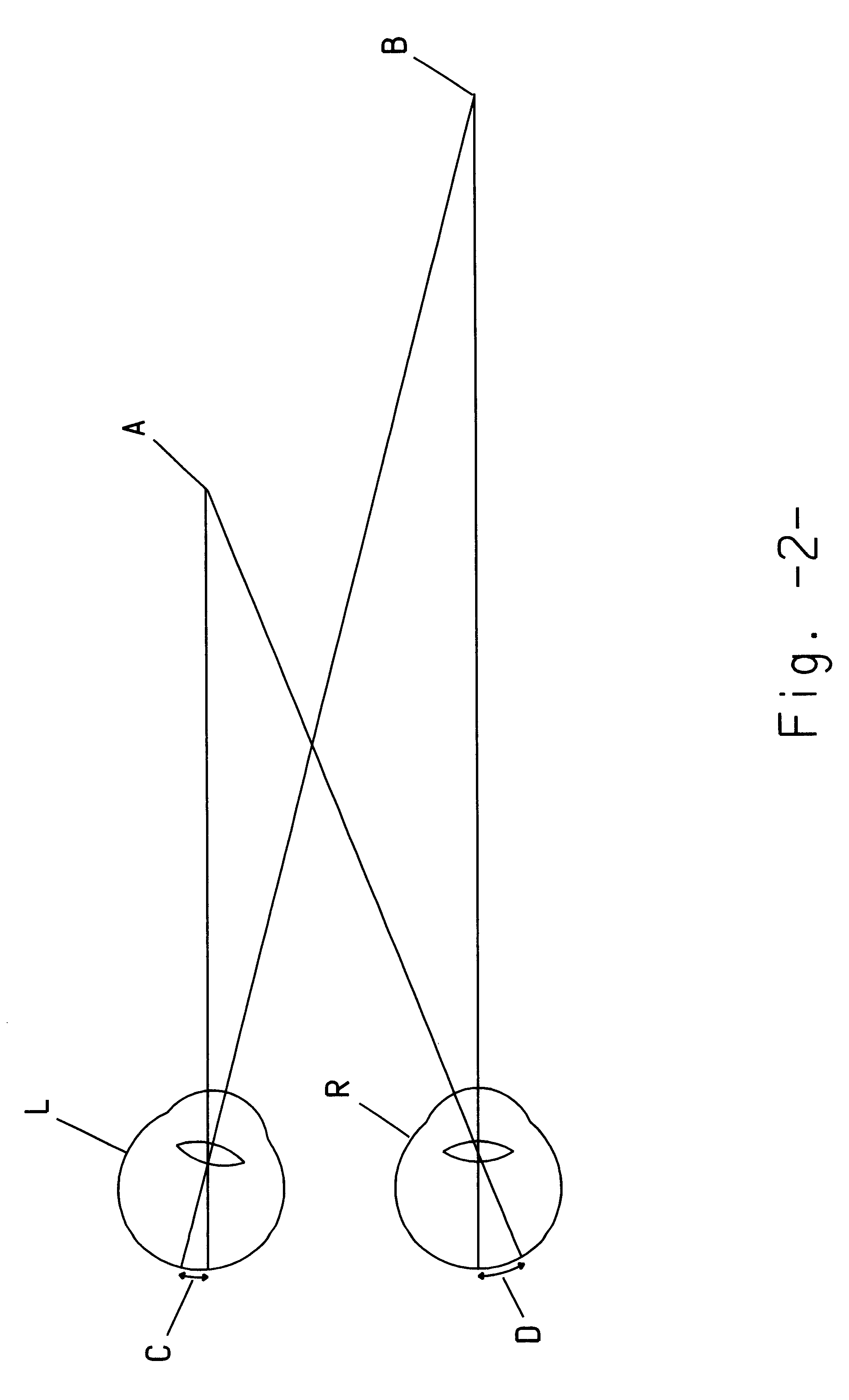
These included: 1) The image acquisition geometry of the stereo-endoscope failed to adequately match the observer's viewing geometry; 2) The left and right eye images were displayed field sequentially, and not simultaneously as would be the case for natural vision; 3) The stereo-monitor displayed an image intended to aid eye-hand co-ordination, but this was not presented at a viewing distance, typically arm's length, where we would normally expect to find an object which we are manipulating; 4) The brightness of the image displayed was compromised, as a result of the field sequential display process.
In International Patent Application PCT / GB97 / 00766 (Street) the problem of barrel distortion, encountered when using wide angle optics, is identified as causing undesirable (for instance vertical) disparity errors in a twin axis stereo-endoscope.

Method used


Image

  • Method and apparatus for improved eye-hand co-ordination during videoscopic surgery
  • Method and apparatus for improved eye-hand co-ordination during videoscopic surgery
  • Method and apparatus for improved eye-hand co-ordination during videoscopic surgery

Examples


Embodiment Construction

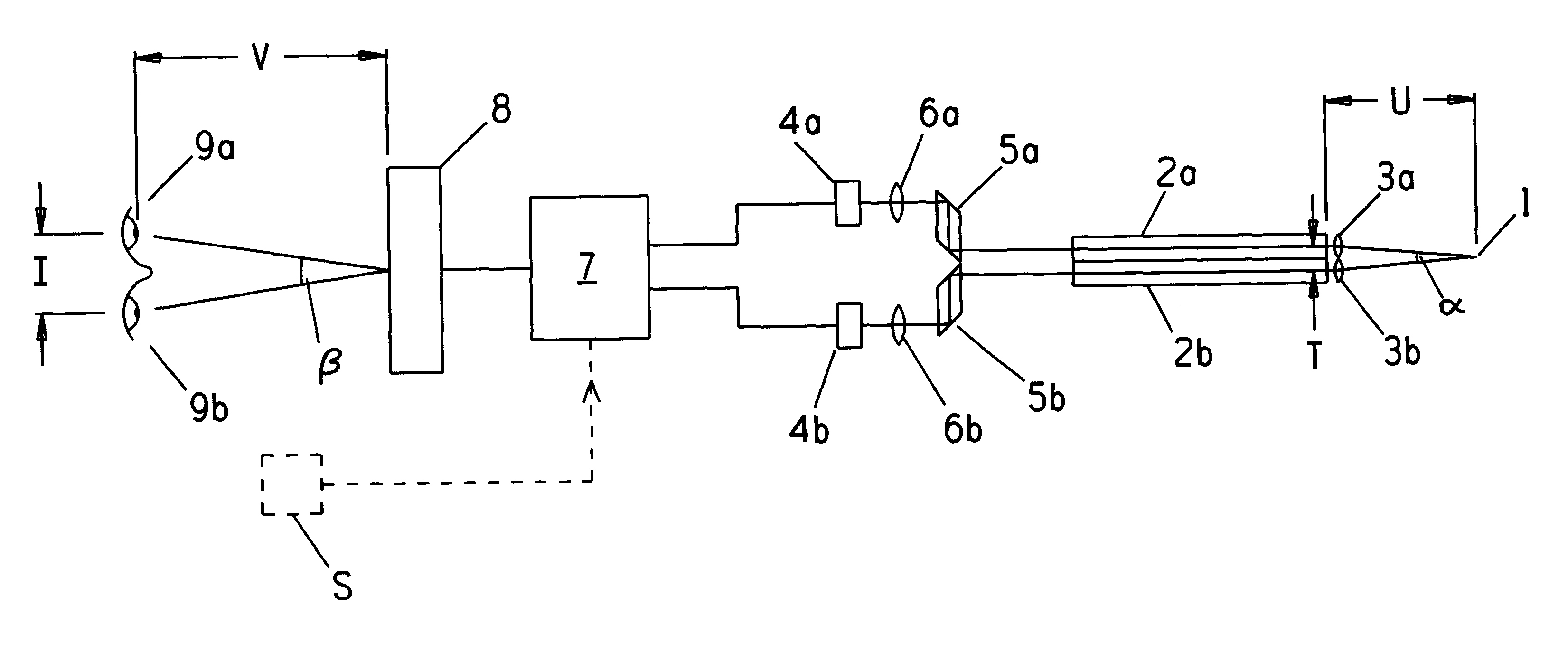
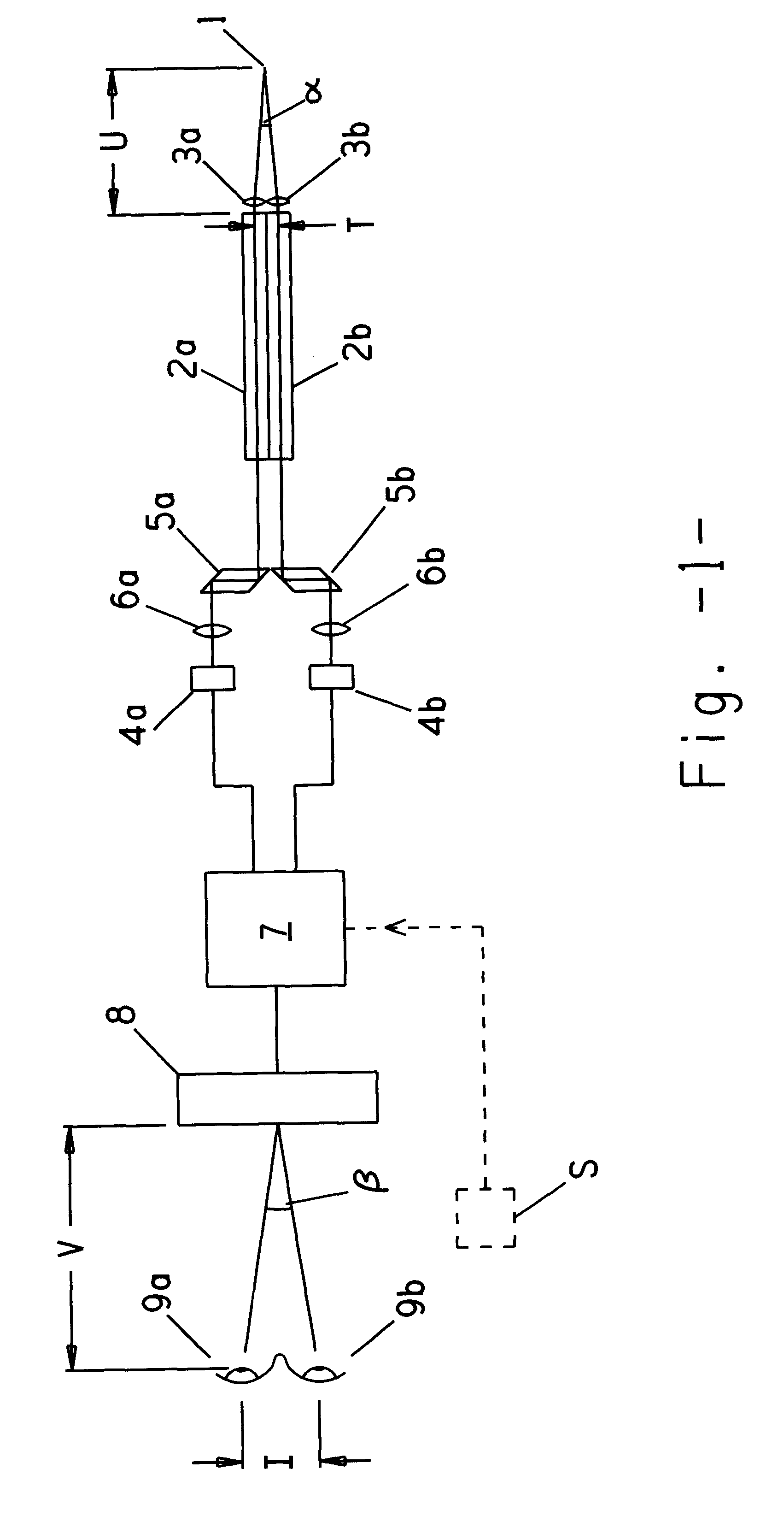
Referring to FIG. 1 there is shown a stereo-endoscope for viewing a point 1 within an object field. The endoscope comprises a pair of optical relay channels 2a, 2b which receive light from the object field, via respective objective lenses 3a, 3b. Each relay channel may comprise coherent fibre optic bundles or a series of relay lenses, in order to relay an image of the object field from the distal end of the channel to its viewing end. Channels 2a, 2b provide respectively for left and right eye views and transmit light to respective CCD cameras 4a, 4b, via prisms 5a, 5b and lenses 6a, 6b. An electronics system 7 takes the camera signals and provides output to a display unit 8, which comprises a back-lit LCD screen and a lenticular array arrangement capable of providing simultaneous co-located and different views of the object field directed to the left and right eyes 9a, 9b of an observer.

At the distal end of the endoscope an angle a is subtended at point 1 by the spacing of the obje...


PUM


Abstract

A stereoscopic image acquisition and display system and associated method, suitable for effective eye-hand co-ordination during videoscopic surgery, is provided. The problems of previous three-dimensional acquisition and display systems are addressed by ensuring that the convergence angle for image acquisition lies within the range of 3 to 16 degrees and that the observer's visual convergence is set within similar limits. Simultaneous display of left and right eye images avoids the problems of field sequential displays. By providing the observer with a displayed image which is sufficiently bright and ensuring that the binocular disparity between corresponding points in the left and right eye images is correct, the system allows the observer to fuse a pair of stereo-images, without causing conflict between visual accommodation and convergence. The location of the displayed image may be adjusted.

Description

This invention is concerned with the field of three-dimensional imaging and in particular with the provision of a natural three-dimensional image of an operative site via, inter alia, an endoscope, thereby improving the eye-hand co-ordination of a surgeon, whilst he / she carries out such a surgical procedure.BACKGROUNDThe field of Minimally Invasive Endoscopic Surgery (MIES) has, for a period in excess of 10 years, been dependent on the use of small diameter viewing devices, collectively known as endoscopes. Some of these are flexible and a majority rigid in construction. A typical working length of the insertion portion of such an instrument would be in excess of 30 cm. The diameter of this part of the instrument will typically vary from 10 mm to as low as 1 mm or less. Small diameter optics or a coherent fibre-optic bundle transfers an image of the operative site, via the distal tip of the insertion portion located inside the patient, to an external CCD camera. The image acquired i...

Claims


Application Information

Patent Timeline
Patent Type & Authority Patents(United States)
IPC IPC(8): A61B1/00H04N13/00
CPCA61B1/00193H04N13/0404H04N13/0239H04N13/305H04N13/239A61B1/00194
Inventor STREET, GRAHAM S. B.
Owner STREET GRAHAM S B
Learn More