
Low resilience, high ink releasing printing surface

a printing surface and high ink technology, applied in the field of low resilience and high ink releasing printing surface, can solve the problems of limiting the amount of ink that may be transferred to the substrate, limiting the printing quality, and affecting the quality of the printed surface, so as to achieve high quality, high speed, and the effect of high percentage of ink applied

Inactive Publication Date: 2003-03-25
MACDERMID PRINTING SOLUTIONS
View PDF8 Cites 10 Cited by
  • Summary
  • Abstract
  • Description
  • Claims
  • Application Information

AI Technical Summary

Benefits of technology

The inventor has found that, independent of the materials used to form the printing surface of the present invention, a high quality image that can be printed on a variety of substrates having different textures at high speeds can be achieved when the printing surface of the printing blanket exhibits certain physical characteristics. Surprisingly, it has been found that a smooth, low-resilience surface described herein has been shown to transfer a much higher percentage of ink applied to it. By transferring more ink, the ink has less opportunity to be emulsified with water, resulting in higher print quality. With less ink remaining on the surface of the blanket there is also less distortion of the dots that is possible due to the forces in the printing nips and sharper, higher resolution images can be produced.
The superior ink-transfer performance of the printing surface 12 as described below is independent of the chemical composition of printing surface 12. Rather, the superior ink-transfer properties of the printing surface 12 are attributed to certain physical characteristics, such as the requisite resilience and smoothness as detailed below.
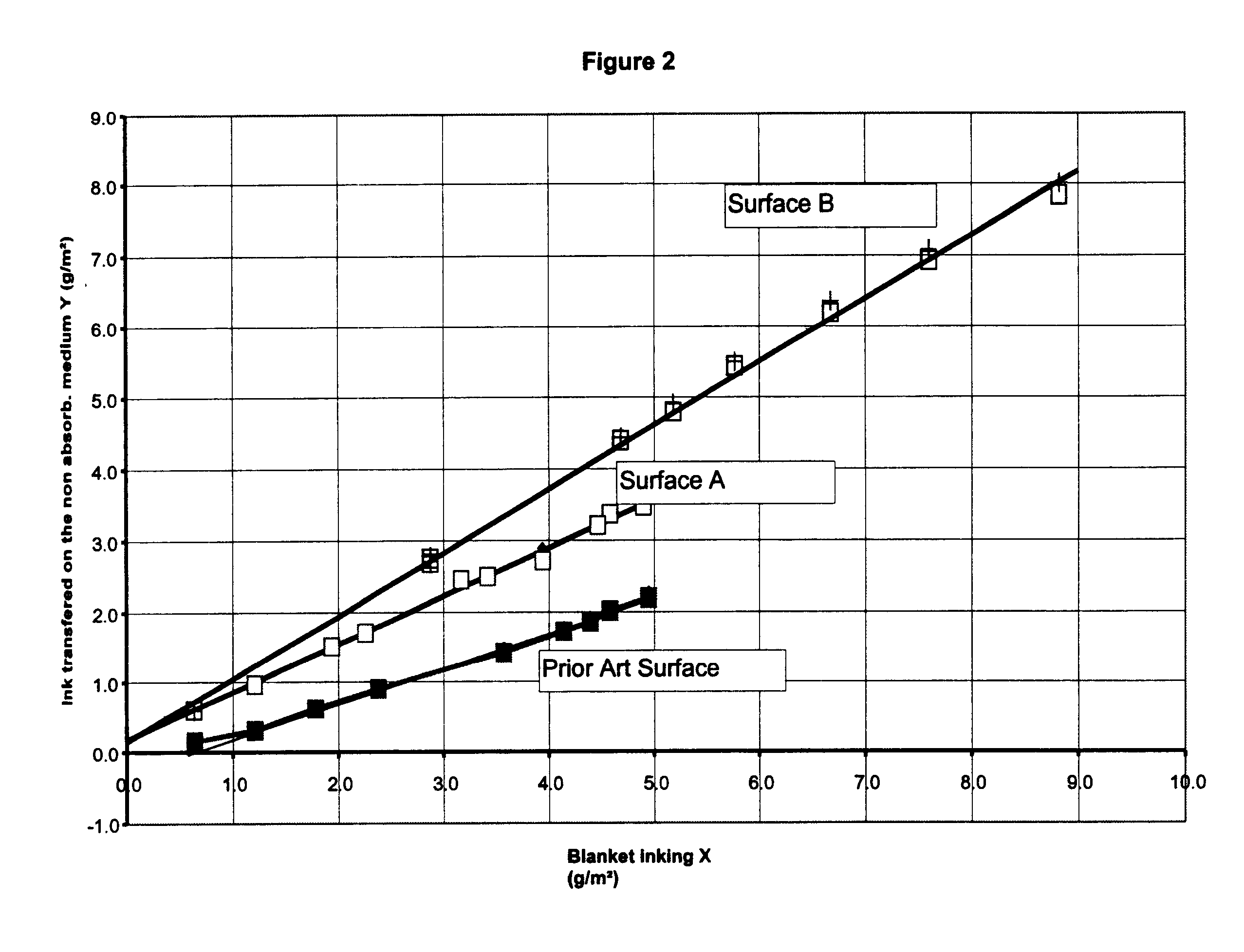
A low-resilient surface will release ink more easily. As used herein, "ink transfer" or "ink release" refers to the percentage of ink that once coated on the surface of the blanket will then be transferred to a substrate on printing. Typically, an IGT standard laboratory printability tester is used to measure ink release. In this case a measured amount of ink is put on the surface of the blanket to be tested. The inked surface is then rolled against a piece of mylar and the amount of ink transferred is then measured. After several tests are done it is possible to plot the amount of ink transferred (Y axis) as a function of the amount of ink applied (X axis). The closer the slope of the line comes to 45 degrees the better the ink transfer. That is, a slope of 45 degrees means that all of the ink applied to the surface of the blanket has been transferred to the substrate. In this test mylar is used as the printing substrate. It is used since it will not inherently absorb ink as would a paper, for example. By avoiding the use of an substrate that would absorb ink then the experimental variability in ink transfer that would create is avoided.
The high ink-releasing surface described here has been shown to transfer a much higher percentage of ink applied to it. By transferring more ink then the ink has less opportunity to be emulsified with water, resulting in higher print quality. With less ink left on the surface of the blanket there is also less distortion of the dots that is possible due to the forces in the printing nips and sharper, higher resolution images can be produced.
Surface smoothness is measured with a profilometer, such as, for example, a Surfometer, commercially available from precision Devices, Inc., Milan, Mich. Such profilometers have become a standard means of describing the surface texture of printing blankets. The technique employed takes a fine stylus, similar to a phonograph needle, and drags it across the surface of the test material. The movement of the stylus as it follows the micro-texture of the surface is then recorded. The results can often be displayed graphically providing a view similar to a high-resolution microscopic cross-section of the surface profile. Typically the device will analyze the surface profile and provide several measures of the roughness. The most commonly used measurement is referred to as the "Ra" or average roughness. The Ra is the arithmetic mean of the profile versus its centerline. The higher the value the rougher the surface. Most normally it has been found that a surface roughness of a buffed surface in the range of about 0.5 to about 0.9 microns provides the best balance between of printing properties. Smoother surfaces (Ra less than about 0.5 microns) generally print sharper dots but ink release and good printing of large areas of solids (areas completely covered by ink) both suffer. At higher roughnesses (Ra greater than about 0.9 microns) a greater amount of ink is carried by the blanket due to its deeper texture having an increased surface area and better printing of solids is achieved. However, at these higher surface roughnesses, sharpness is sacrificed.

Problems solved by technology

That means that some ink remains on the blanket and is over-coated with additional ink on subsequent rotations of the printing press.
The ink that stays on the blanket will increase in tack level (i.e., adhesiveness) the longer it stays on the blanket, further limiting the amount of ink that may be transferred to the substrate.
This phenomenon typically limits print quality since ink that stays on the blanket is also continuously exposed to water.
Also, on each revolution of the printing press the ink left behind on the blanket is exposed to compression and shear forces when pressed against the substrate or against the printing plate.
This tackiness makes release from an extremely smooth surface more difficult.
Increasing surface roughness, however, limits the printing sharpness that can be achieved.
Smooth surfaces generally release ink poorly and unevenly on a microscopic scale.
Both of these techniques are limiting in the quality of the solids printed or in the sharpness of the dot printed.
Additionally, it is believed that, a low resilience printing layer would require a highly textured surface which then would adversely effect print sharpness.
The reasoning is that a highly textured surface would carry a thicker ink film and so compensate for the loss of contact time in the printing nip due to the poor ability of the low resilience printing layer to stay in intimate contact with the printing substrate.
High resiliency of the blanket's printing layer, however, has become a problem with increased demand for higher speed printing.
As printing press speeds have increased, it has become more difficult to achieve high print quality.
Higher printing speeds mean that the press cylinders are spinning faster, thus, the ink used must have a higher adhesion or "tack" level to stick to the blanket, plate, and inking cylinders, otherwise the ink is sprayed off of the cylinders and can not print well.
The problem is that, as described above, as ink tack levels are increased, it becomes increasingly harder to then transfer the ink from the blanket onto the paper or other printing substrate.
The result is to hinder release of the ink.
A low resilient surface, however, will not move quickly in being pulled upward from the blanket surface and, so, will release ink faster.
As press speeds are increased a highly resilient surface will continue to respond quickly to the forces the ink is putting on the surface and will make ink release more difficult as ink tack levels are increased for the higher press speeds.
It is speculated that a low resilient surface will be unable to keep up with the faster motions the ink is experiencing at higher speeds and so will put added force on the ink, forcing it to release easily.
Thus, it is believed that, ultimately, a highly resilient blanket surface will not act to improve ink release at higher speeds and a low resilient surface will.
This conclusion, however, is counter to the accepted art that has driven towards increased resilience in blanket surfaces and other components for higher speed applications.
In actuality, the result of the use of highly resilient blanket materials leads to a very limited operating window on press as to acceptable ink tack levels and has lead to a reduction in print quality on high speed printing.
That improvement in release has allowed heretofore impractical degrees of surface smoothness to be used that would otherwise have provided very poor ink release, giving poor print quality.
High resiliency of the blanket's printing layer is also an issue with respect to the substrate to which the ink is being transferred.
Glossy paper, however, is very smooth and makes the release more difficult.
Release of the ink then becomes very difficult with traditional, resilient blanket surfaces and the ultimate print quality is limited.

Method used


Image

  • Low resilience, high ink releasing printing surface
  • Low resilience, high ink releasing printing surface
  • Low resilience, high ink releasing printing surface

Examples


Embodiment Construction

A Composition According to the Present Invention

A low-resilience printing surface according to the present invention can be made by compounding the following ingredients in a rubber mill:

A solvent such as toluene is added and the low-resilience printing surface layer can be prepared using a solvent cast technique to coat a transfer medium such as a mylar sheet and then permitting the material to dry. In the alternative, the surface layer can be solvent cast directly onto the blanket carcass that has been coated with an adhesive, dried and cured at about 300.degree. F. The thickness of this surface material can be from about 4 mils to about 15 mils thick, preferably about 8 mils to about 12 mils thick, and most preferably about 10 to about 12 mils. When using a transfer sheet, the sheet with the compound side down, is placed onto the carcass and adhesively attached thereto. An appropriate adhesive would be easily determined by one of ordinary skill in the art. In addition to the solv...


PUM


Abstract

Novel printing surfaces for off-set printing blankets are provided having a resilience of less than about 40% and an average surface roughness of less than about 0.5 microns. Such low-resilience printing surfaces have been found to transfer up to greater than 90% of the ink applied thereto and can be used to transfer ink on a wide variety of substrates.

Description

The present invention relates to printing blankets of the type used in offset lithography, and more particularly to the use of a printing blankets having a low-resilience printing surface.An offset printing blanket is used to transfer ink and fountain solution (primarily water) to paper or other substrates from a printing plate on a printing press. It can also serve a similar function in transferring other coatings including, for example, varnishes. As used herein, the term "ink" refers to any printing fluids or coating. Also, the term "printing blanket" as used herein refers to any of the forms that may achieve the same basic function of printing. Printing blankets are typically wrapped around a cylinder and the paper is either sheet feed or fed on a web between the rollers.The role of a printing blanket is to transfer dots of ink and water films from a printing plate in an offset press to a substrate (typically but not exclusively paper). The surface of the blanket must have a nat...

Claims


Application Information

Patent Timeline
Patent Type & Authority Patents(United States)
IPC IPC(8): B41N10/00B41N10/02
CPCB41N10/02Y10S428/909B41N2210/06B41N2210/14B41N2210/10B41N2210/02
Inventor RODGERS, RICHARD
Owner MACDERMID PRINTING SOLUTIONS
Learn More