
Fuel injection valve for internal combustion engines

a technology for internal combustion engines and fuel injection valves, which is applied in the direction of fuel injection pumps, machines/engines, mechanical equipment, etc., can solve the problems of entail a large force expenditure for moving the control valve member

Inactive Publication Date: 2003-03-04
ROBERT BOSCH GMBH
View PDF9 Cites 9 Cited by
  • Summary
  • Abstract
  • Description
  • Claims
  • Application Information

AI Technical Summary

Benefits of technology

The fuel injection valve of the invention as defined by the characteristics of claim 1 has the advantage over the prior art that the motion of the control valve member for connecting the control pressure chamber to the relief chamber need not take place counter to the pressure in the control pressure chamber, and thus only slight force is required to move the control valve member. This makes it possible to use a piezoelectric actuator of slight dimensions, and thus the structural size and the weight of the control valve can be kept small and low, respectively. Furthermore, by means of the control valve member, the opening stroke of the injection valve member can be limited in an infinitely graduated way.Advantageous features and refinements of the fuel injection valve of the invention are defined by the dependent claims. By means of the embodiment defined by claim 2, secure closing of the conduit at the closing piston by the control valve member is achieved, if the piezoelectric actuator is not activated. By means of the spring provided in accordance with claim 3, the force the piezoelectric actuator must exert to move the control valve member counter to the restoring spring is reduced.

Problems solved by technology

The motion of the control valve member by means of the piezoelectric actuator must take place counter to the pressure prevailing in the control pressure chamber, so that moving the control valve member entails a major expenditure of force.

Method used


Image

  • Fuel injection valve for internal combustion engines
  • Fuel injection valve for internal combustion engines
  • Fuel injection valve for internal combustion engines

Examples


Embodiment Construction

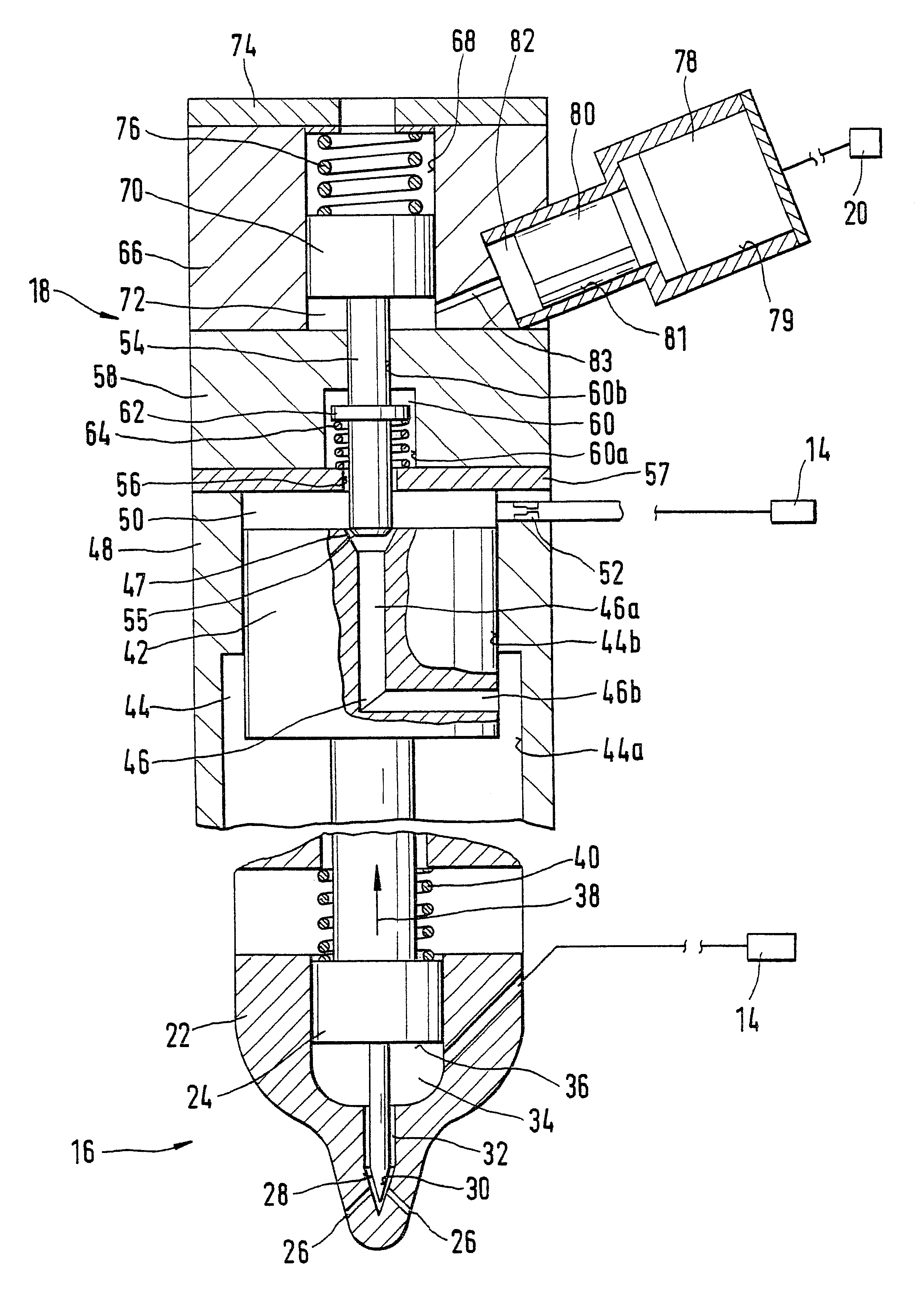
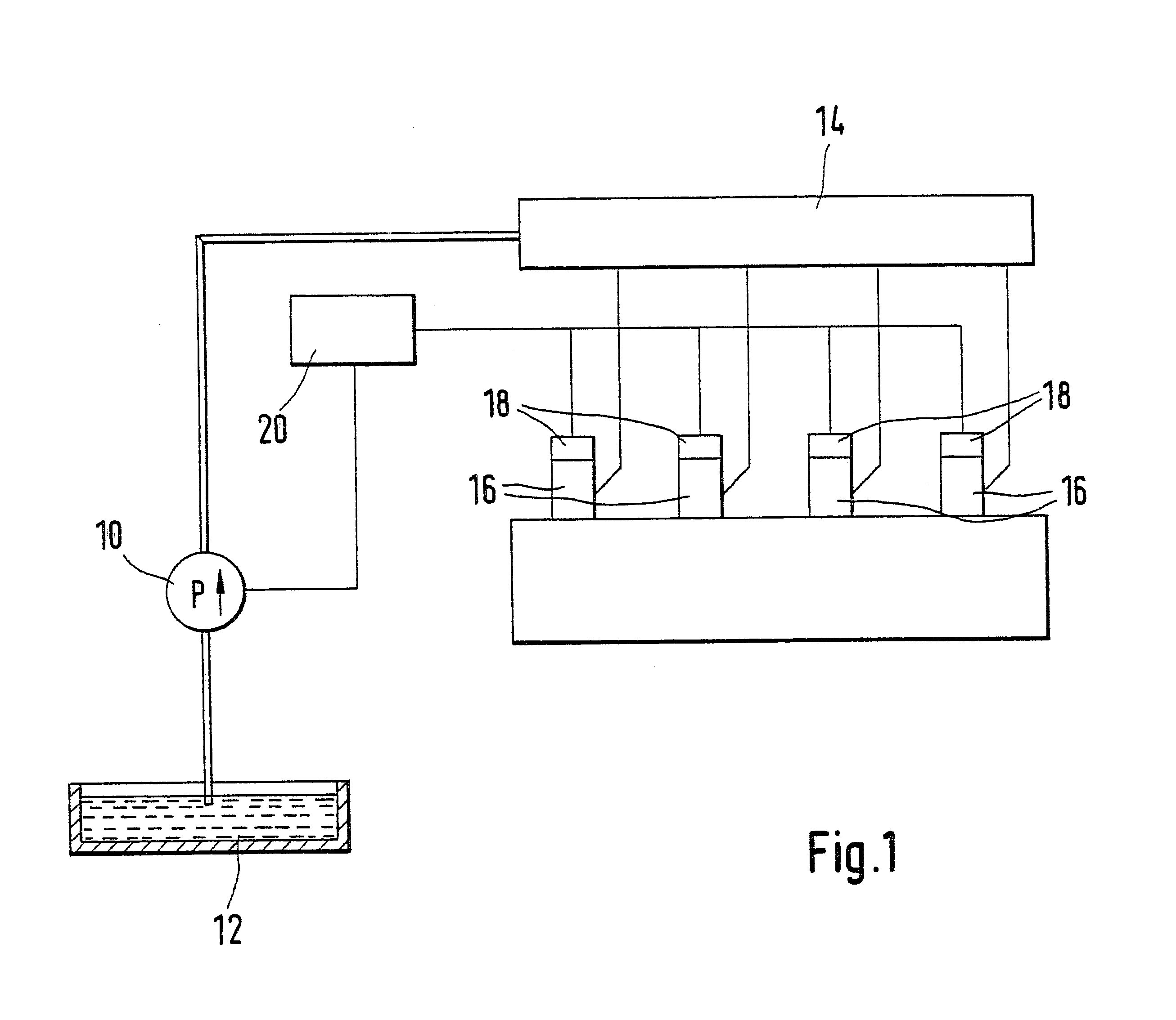
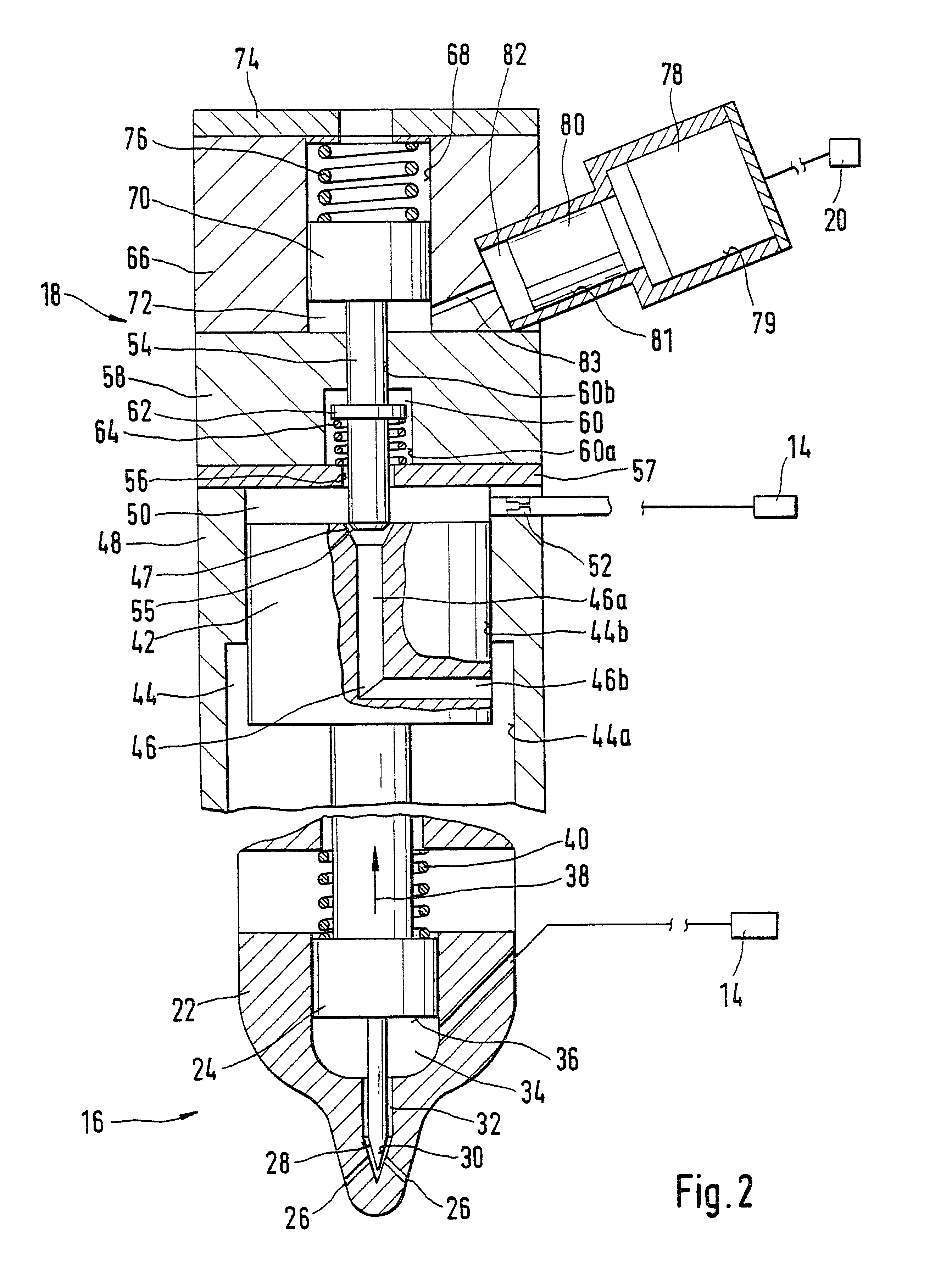
A reservoir-type fuel injection system schematically shown in FIG. 1 has a high-pressure pump 10, by which fuel is pumped at high pressure from a tank 12 into a reservoir 14. The reservoir 14 is embodied as a so-called rail, from which lines lead away to fuel injection valves 16 disposed in an internal combustion engine. Each fuel injection valve 16 has one control valve 18, by which the opening and closing of the fuel injection valve 16 is controlled. The reservoir-type fuel injection system furthermore has a control unit 20, which is supplied with signals about various operating parameters of the engine and by which, as a function of these signals, the control valves 18 of the fuel injection valves 16 are triggered to open or close the fuel injection valves.

In FIG. 2, one fuel injection valve 16 is shown with its associated control valve 18. The fuel injection valve 16 has a valve body 22, in which an injection valve member 24 is guided axially displaceably. The valve body 22, in ...


PUM


Abstract

The fuel injection valve (16) has an injection valve member (24), by which at least one injection opening (26) is controlled.The motion of the injection valve member (24) is varied by a control valve (18) that has a control valve member (54) by which the pressure in a control pressure chamber (50) is controlled in that the control valve member controls a relief chamber (46) in a closing piston (42) that defines the control pressure chamber (50) and that by means of the pressure prevailing in the control pressure chamber (50) urges the injection valve member (24) in its closing direction. The control valve member (54) is displaceable via a hydraulic boost by a piezoelectric actuator (78), as a result of which the piezoelectric actuator opens or closes the relief chamber (46). The control valve member (54) cooperates as a valve seat with the orifice (47) of the relief chamber (46) at the closing piston (42), and its cross-sectional area in the control pressure chamber (50) is at least approximately equal to the cross-sectional area of the orifice (47) of the relief chamber (46), so that because of the pressure in the control pressure chamber (50), no force is exerted on the control valve member (54), and only a slight force is required to displace it.

Description

PRIOR ARTThe invention is based on a fuel injection valve for internal combustion engines as generically defined by the preamble to claim 1.One such fuel injection valve is known from German patent disclosure DE 198 13 983 A1. This fuel injection valve is a component part of a reservoir-type fuel injection system and has an injection valve member by which at least one injection opening is controlled and which has a pressure shoulder that defines a pressure chamber. Fuel under pressure can be delivered to the pressure chamber from a high-pressure fuel source via a pressure line, by which fuel the injection valve member can be lifted from a valve seat counter to a closing force to open the at least one injection opening. The motion of the injection valve member is varied by a control valve that has a piezoelectric actuator-actuated control valve member, which controls a pressure, prevailing in a control pressure chamber that communicates with a pressure source, that urges the injectio...

Claims


Application Information

Patent Timeline
Patent Type & Authority Patents(United States)
IPC IPC(8): F02M47/02F02M63/00F02M47/00F02M51/00
CPCF02M47/025F02M2200/703F02M2200/21F02M59/46
Inventor STOECKLEIN, WOLFGANG
Owner ROBERT BOSCH GMBH
Learn More