Flow rate and flow velocity measurement device

Inactive Publication Date: 2003-03-04
NGK SPARK PLUG CO LTD
View PDF12 Cites 72 Cited by
  • Summary
  • Abstract
  • Description
  • Claims
  • Application Information

AI Technical Summary

Benefits of technology

In this measurement device, in the divided flow pipe, a measurement fluid introduced into the divided flow pipe is sharply changed in its direction before it arrives an inlet of the branch flow passage in which the detection element exists. Therefore, the pollution substance whose inertia is high is prevented from entering into the branch flow passage in which the detection element exists. In addition, in the divided flow pipe, by means of further dividing the flow by the partition, it is possible to reduce a Reynolds number of the flow toward the detection element (because a flow sectional area becomes small), so that the flow in the vicinity of the detection element is adjusted and it is possible to perform a high accuracy detection. That is, according to this measurement device, by effectively branching the measurement fluid and changing it in its direction, in regard to both of the pollution substance mixed in the measurement fluid whose density is higher than that of the measurement fluid and the pollution substance whose density is relatively low, these pollution substances are all prevented from accumulating on a detection face of the detection element, so that there is provided a measurement device which is excellent in pollution resistance and whose detection output change is low over a long period.
A measurement device of a third aspect of the invention has: a detection element which is disposed so as to be exposed to a flow in, among the plural branch flow passages, the branch flow passage formed in an inner peripheral side or an intermediate portion of the divided flow pipe, and detects a quantity concerning the flow; and a throttle formed in a flow passage between an inlet port of the divided flow pipe and an inlet of the branch flow passage in which a detection face of the detection element is exposed to the flow therein. In this manner, in case where the detection element is exposed to the branch flow passage of the inner peripheral side or the intermediate portion in which a direction change of the flow introduced into the divided flow pipe inlet port is relatively small in comparison with the branch flow passage of the outer peripheral side, the accumulation of the pollution substance onto the detection element is suitably prevented by providing the throttle.
In the preferred implementation mode of the invention, an end portion of the partition does not extend to just below the inlet port of the divided flow pipe, and an inlet of the outer peripheral side branch flow passage in which the detection element is exposed to the flow therein does not open just below the inlet port of the divided flow pipe. By this, the pollution substance is prevented from advancing straight from the divided flow pipe inlet port toward the branch flow passage inlet.
In the preferred implementation mode of the invention, there is formed a bypass flow passage short-circuiting between the inlet port and the outlet port of the divided flow pipe without passing through the plural branch flow passages. By this, the flow introduced into the divided flow pipe is stabilized and, further, the measurement fluid (flow in the main flow pipe) becomes easy to be taken into the divided flow pipe. Especially, in case where the flow passage structure of the divided flow pipe is formed symmetrically with the detection element being made a center, by providing an orifice reducing the bypass flow passage or a flow sectional diameter of the bypass flow passage, it is possible to intend to stabilize the flow reaching the detection element in regard to both of the normal flow and the reverse flow.
In the preferred implementation mode of the invention, in the divided flow pipe, there is provided means for forming such a flow as obliquely impinging against a detection face of the detection element. By this flow control means, a flow to be detected is constantly supplied to the detection face of the detection element, so that it is considered that it follows that the flow to be detected surely flows on the detection face. In addition, since generations of vortex flow and exfoliation in the vicinity of the detection face are suppressed, it is considered that a detection accuracy and a reproducibility are improved.

Problems solved by technology

In an engine combustion controlling mass flow rate sensor for a vehicle, an output change due to a pollution substance accumulation onto a detection element is a great problem.
However, the housing structure of a sensor disclosed in the Japanese Patent Laid-Open No. 193863 / 1996 Gazette is effective for accumulation prevention of a pollution substance whose density is much higher than that of a measurement fluid but, as to the pollution substance whose density is relatively low, there is a fear that it enters into a divided flow passage and is accumulated onto the detection element.
Further, in this sensor, since it is excessively intended to exclude an influence of the reverse flow, it becomes difficult to measure the reverse flow.

Method used


Image

  • Flow rate and flow velocity measurement device
  • Flow rate and flow velocity measurement device
  • Flow rate and flow velocity measurement device

Examples


embodiment 5

1 with Embodiment 5

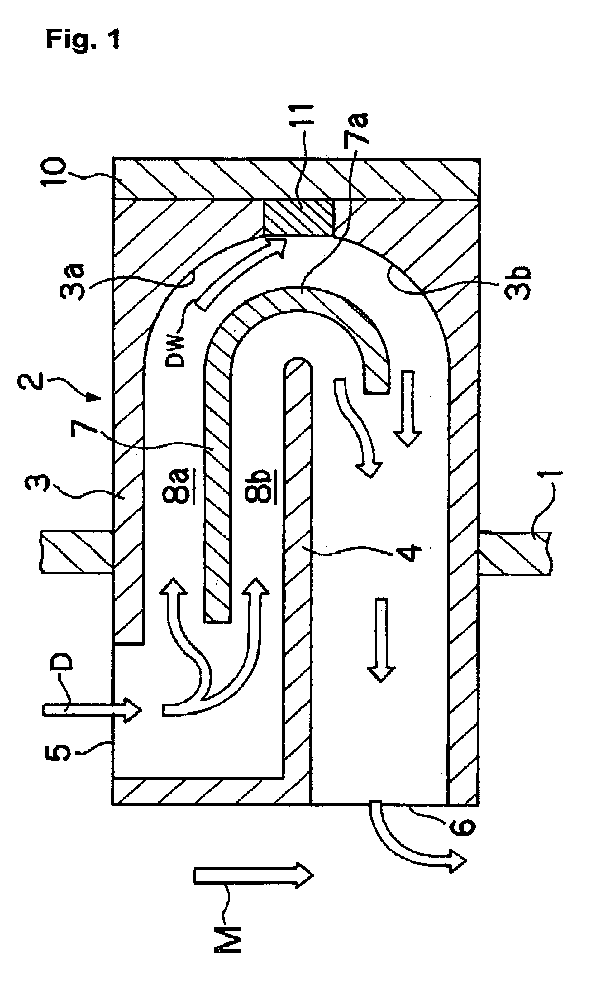
Next, especially as to the measurement of the reverse flow, a sensor (detection) output of a measurement device of a Comparison Example 1 and a sensor output of the measurement device of the Embodiment 5 are explained in comparison. First, a structure of the measurement device of the Comparison Example 1 is explained mainly concerning points of difference from the measurement device of the Embodiment 5. FIG. 10 is an explanatory view of the measurement device of the Comparison Example 1, and shows a longitudinal section along the axis direction of the main flow pipe. Referring to FIG. 10, in the pipe wall of the main flow pipe 1, a divided flow pipe 52 is mounted orthogonally to the pipe axis direction of the main flow pipe 1 so as to be able to take in the divided flow D separated from the main flow M. Within the divided flow pipe 52, a divided flow pipe passage curved approximately in .OMEGA.-shape form is formed by an inner wall 54 (main separator). In an outer...


PUM


Abstract

A flow measurement device is disclosed, in which an accumulation of pollution substance onto a detection element is prevented, and which can measure a reverse flow similarly to a normal flow. On both ends of an outer wall 23 outer peripheral portion of a divided flow pipe 20 having a OMEGA-shape pipe passage, there are oppositely formed an inlet port 25 and an outlet port 26, which open in faces orthogonal to a flow direction of a main flow M that is a detection object. Within the divided flow pipe 20, by a curved partition 27, plural branch flow passages 28a, 28b mutually branching and joining in the divided flow pipe 20 are formed. Inside both end portions of the outer wall 23, undulation portions 32, 33 are formed so as to clog an inlet and an outlet of the outer peripheral side branch flow passage 28a and, by this, throttles are formed respectively in a flow passage between the inlet port 25 and the inlet of the branch flow passage 28a and a flow passage between the outlet port 26 and the outlet of the branch flow passage 28a. In a bottom portion of the outer wall 23 of the divided flow pipe 20, a detection element 31 is attached so as to be exposed to a flow in the outer peripheral side branch flow passage 28a and, against its detection face, a down flow DW further divided from a divided flow D obliquely impinges.

Description

1. Field of the InventionThe present invention relates to a device for measuring various quantities concerning a flow, among others, relates to a flow rate and flow velocity measurement device using a detection element integrally formed on a detection element and / or a semiconductor chip depending on temperature, and relates to a measurement device suitably applied, for example, as a combustion controlling mass flow rate sensor of an engine for a vehicle or industry, or a mass flow rate sensor for an industrial air conditioning system and compressor pressurized air supply system and, furthermore, an air / fuel ratio controlling flow rate sensor of a domestic gas hotplate.2. Description of the Related ArtIn an engine combustion controlling mass flow rate sensor for a vehicle, an output change due to a pollution substance accumulation onto a detection element is a great problem. In order to solve this problem, in Japanese Patent Laid-Open No. 193863 / 1996 Gazette and the like there is pro...

Claims


Application Information

Patent Timeline
IPC IPC(8): G01F1/684G01F1/48
CPCG01F1/6842G01F1/48
Inventor MAEDA, SHUNSUKEKOHMURA, YOSHIHIKOKOJIMA, TAKIOKUZUYA, YASUHISASUDA, MASANORIOSHIMA, TAKAFUMI
Owner NGK SPARK PLUG CO LTD
Why Eureka
Try Eureka