
Method of transmitting and receiving data, system and receiver therefor

Inactive Publication Date: 2003-02-18
LO JACK CORPORATION
View PDF4 Cites 76 Cited by
  • Summary
  • Abstract
  • Description
  • Claims
  • Application Information

AI Technical Summary

Benefits of technology

The frequency of the transmitted data signal may be varied between successive transmissions. This ensures that a good signal will be received even if there is line interference at a particular frequency as the subsequent transmission will be at a frequency which is unlikely to be affected by the same interference.
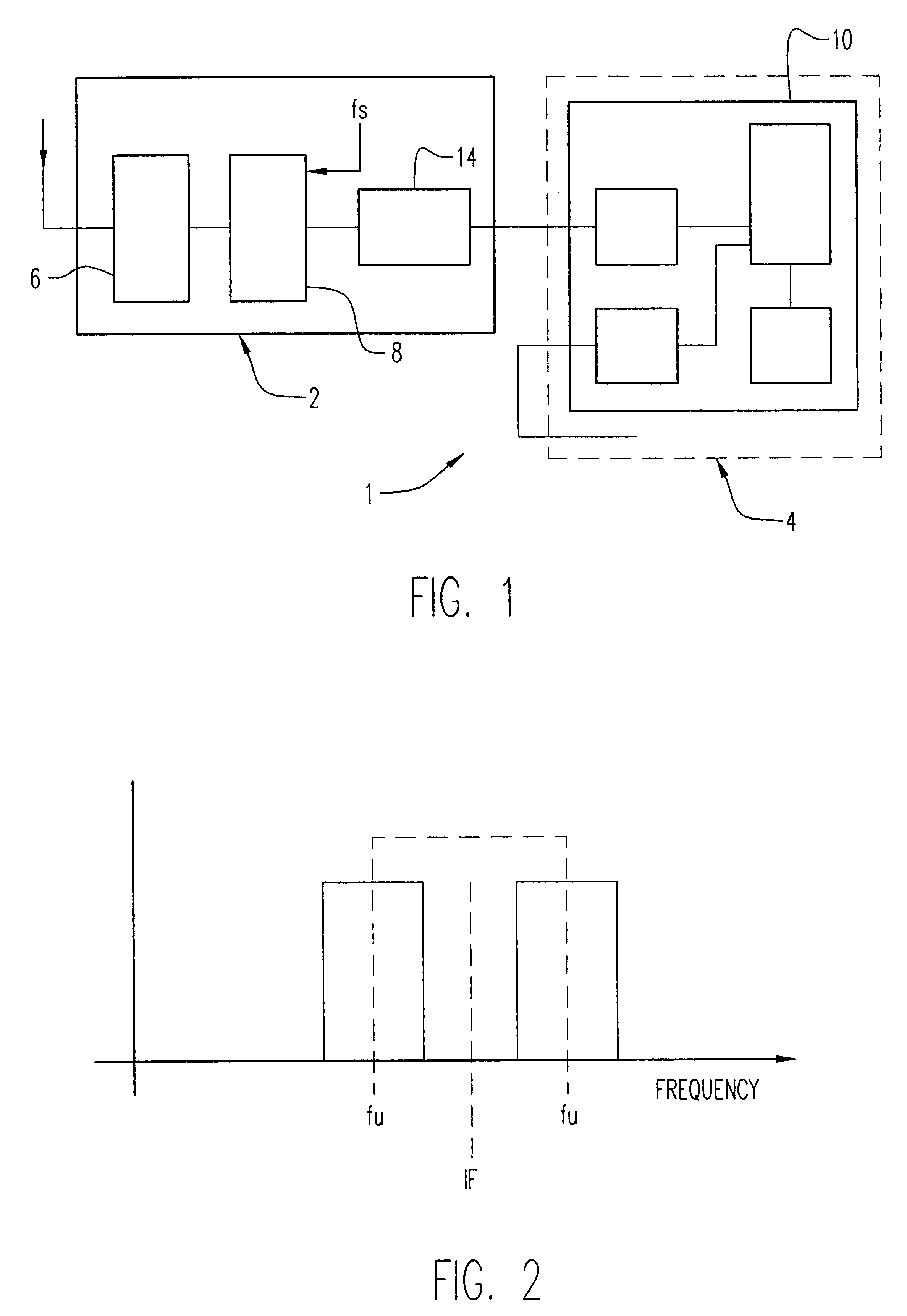
An embodiment of the present invention increases the effective range of the transmitter by providing, in effect, narrow band communication between the transmitter and the receiver. This increases the range for the same power, but at some decrease in the rate of data transmission which can be used. As this narrow band communication is provided by the signal processing techniques at the receiver, it is not necessary to provide a more accurate, and therefore more costly, narrow band transmitter.
Preferably, it is required that both the leading and trailing flag sequences are detected to verify the presence of a data packet. This greatly reduces the possibility of false detections. Furthermore, the frequency and timing information for the demodulation step is determined from the flag sequences. The presence of a flag sequence before and after each data packet enables the frequency and timing to be used during demodulation to be re-measured at regular intervals.
The data signal may have plural data packets separated from each other by flag sequences. Thus, where there are n data packets, there would be n+1 flag sequences in the data signal. The use of flag sequences to provide a means of detecting the presence of data, and to provide frequency and timing information to enable its demodulation, means that external synchronisation between the transmitter unit and a receiver is not required.
By enabling true two-way data communication between a base station (which may be relatively high power and expensive) and a plurality of transceivers (which may be low power and cost), the present invention greatly enhances the value and usefulness of a digital communications system. For example, when a transceiver has been activated by a base station, the transceiver can send a data signal to the base station to acknowledge that it has been activated, thus providing assurance to the base station that the activation signal has been received and saving the base station from having to repeat the signal many times to ensure that it had been received as in the past. A de-activation signal may be sent to the transceiver which can also be acknowledged by the transceiver so that the base station can be confident that the de-activation signal has been received and thus preventing false or erroneous activations from being maintained. Data concerning the status of the transceiver (such as the status of the transceiver unit, its battery voltage, etc.) can be sent to the base station which can therefore continually monitor the status of the transceiver unit. From time to time, the base station can send test signals to each of the transceiver units to ensure that the units are working properly, with the transceiver units being able to respond appropriately; in the prior art vehicle tracking system described above, for example, the only way of testing a transceiver unit was by bringing the vehicle in on a regular basis for servicing and testing each unit by making physical connections to the unit during each service.

Problems solved by technology

Such two-way or duplex communication is not possible with the known system because of the disparity in the power available from an on-board transceiver unit and from a base station.
The on-board transceiver units each have a transmitter whose power is 1 watt and with a maximum range of 1.5 miles (about 2.5 km), which is often not sufficient to reach a base station.
It is not possible simply to increase the power of the on-board transmitter units as this would increase their size and their cost, and this is not acceptable to the market.
Normally, the use of a reduced bandwidth transmitter unit would increase the cost of each on-board transceiver unit because high accuracy components in the transceiver unit would be required.
However, the market will not accept units having a significantly higher cost and therefore high accuracy components cannot be used in such a transceiver.
As the frequency of transmission used by each mobile transceiver is therefore critical to it being properly identified by the base station, it is essential that the base station transmits timing synchronising signals to the mobile transceivers and the mobile transmitters accordingly have to be relatively complex (and therefore expensive) in that they must contain memories and circuits so that the correct frequency and pattern of frequency hopping is transmitted by each mobile transceiver.
Furthermore, the signals transmitted by the mobile transceivers are not modulated with and therefore do not contain any data to be transmitted to the base station because the only information used by the base station is the fact that a particular identified mobile transceiver is actually transmitting.

Method used


Image

  • Method of transmitting and receiving data, system and receiver therefor
  • Method of transmitting and receiving data, system and receiver therefor
  • Method of transmitting and receiving data, system and receiver therefor

Examples


Embodiment Construction

The receiver and telecommunication systems described herein have general application. However, for clarity, the systems and methods are specifically described when used in a tracking system for recovering stolen vehicles. It is to be understood, however, that the invention is not limited to such a tracking system. For example, the present invention may be applied to remote metering of electricity or other utility meters; low data rate telemetry from remote (e.g. non-mains powered) installations such as water reservoirs; from personal or property accident or attack security alarms such as rape alarms, mountain rescue alarms, etc.; security systems for buildings, low-power wireless alarms, connection of building alarms to a national central monitoring system; remote controls for example in a domestic environment such as for electrical appliance control; and non-radio communications system using, for example, signalling via electricity mains supply.

The techniques described in detail be...


PUM


Abstract

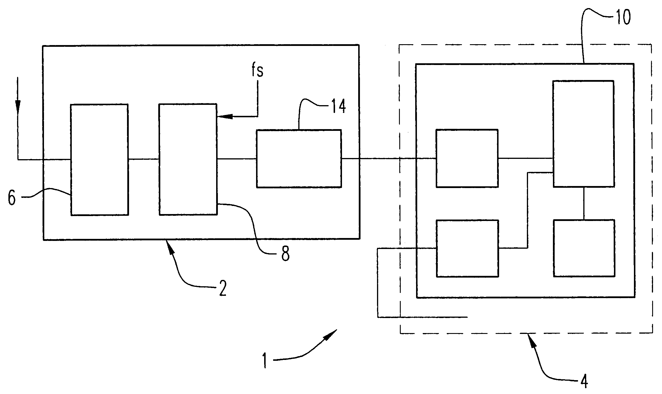
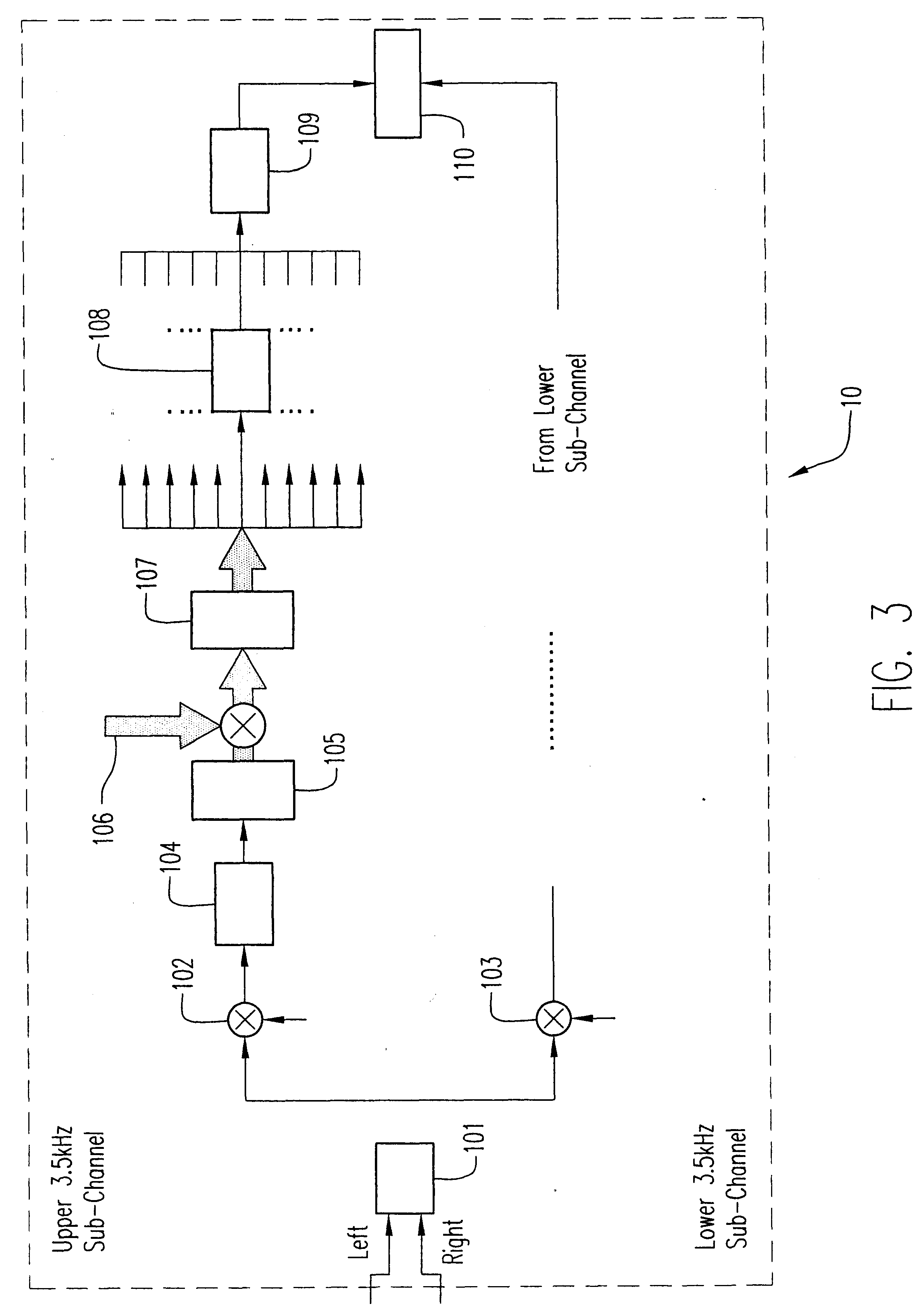
A method and apparatus for transmitting and receiving data, wherein a narrow band data signal is transmitted at an unknown frequency within a known range of frequencies and received, and, at the receiver, the range of frequencies is divided into plural frequency bands each of width less than the uncertainty in the transmission frequency of the data signal, with the presence of said data signal detected in at least one of said frequency bands and thereupon demodulated.

Description

The present invention relates generally to a method of digital communication and to a digital communication system.BACKGROUND OF INVENTIONThe applicant's known vehicle tracking system, which is in use in the United Kingdom, allows the police to track and recover stolen vehicles. In this known system, a small transceiver unit is hidden in a vehicle. The unit is activated by an activation signal to transmit signals when the vehicle is stolen. The activation signal is generated from a network of base stations. Police vehicles are fitted with receivers, which enable them to receive the signals transmitted by the transceiver unit in the stolen vehicle. In this manner, the police can track, locate and recover the vehicle.Additional and more sophisticated functions could be incorporated in the tracking system if there were a two-way link between the transceiver unit in each vehicle and a base station, usually the nearest base station, with that base station acting additionally as a receive...

Claims


Application Information

Patent Timeline
IPC IPC(8): G01S1/00G01S1/04H04B1/38H04B1/26
CPCG01S1/045H04B1/3827H04B1/26
Inventor IRVING, CLIVE RUSSELLSPREADBURY, DAVID JOHNSMITHERS, COLIN RICHARDMACE, TIMOTHY CHARLES
Owner LO JACK CORPORATION
Learn More