
Spin valve sensor with composite pinned layer structure for improving biasing of free layer structure with reduced sense current shunting

a sensor and composite technology, applied in the field of spin valve sensor with composite pinned layer structure, can solve the problems of difficult counterbalance, exacerbated problems, and more difficult to properly bias the free layer

Inactive Publication Date: 2003-02-11
HITACHI GLOBAL STORAGE TECH NETHERLANDS BV
View PDF2 Cites 27 Cited by
  • Summary
  • Abstract
  • Description
  • Claims
  • Application Information

AI Technical Summary

Benefits of technology

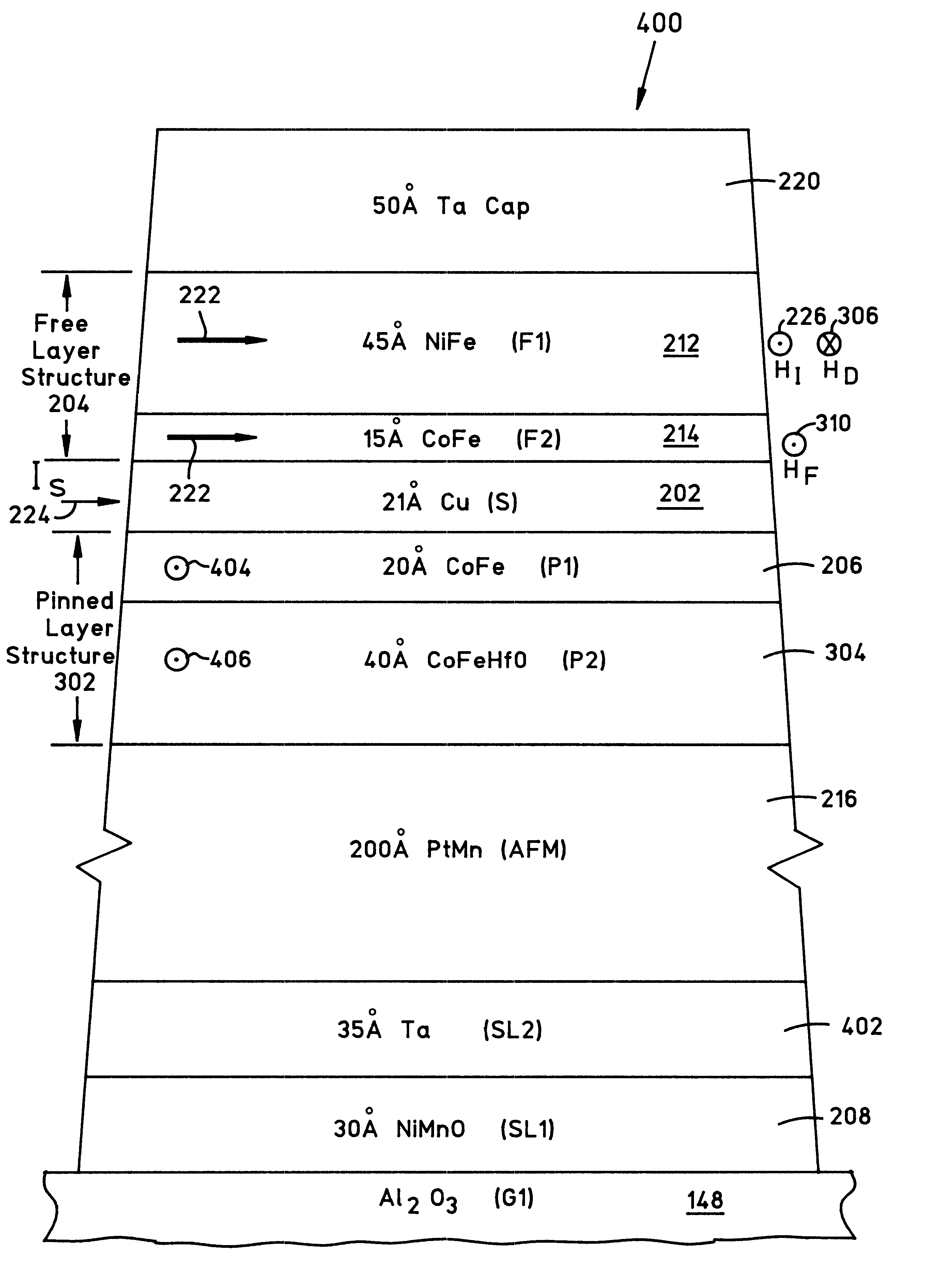
Another object is to provide a pinned layer structure wherein magnetoresistance of a spin valve sensor is increased by having a cobalt based first layer interfacing a spacer layer and a second layer, which has a cobalt iron (CoFe) constituent, for still further increasing magnetoresistance, and hafnium (Hf) and oxide contents for providing a high resistance for minimizing sense current shunting and the oxide content for specular reflection of conduction electrons so as to further improve the magnetoresistance.

Problems solved by technology

Since the conductive material on the pinned layer side of the free layer is significantly greater than the conductive material on the other side of the free layer the sense current fields from the pinned layer side are a major force on the free layer which is difficult to counterbalance with the other magnetic forces acting on the free layer.
If the pinned layer is an antiparallel (AP) pinned layer structure instead of a single pinned layer the aforementioned problems are exacerbated.
Since an AP pinned structure has more conductive material on the pinned side of the free layer than a single pinned layer the sense current field on the free layer is increased from the pinned layer side of the free layer as compared to a single layer simple pinned spin valve sensor and it is therefore still more difficult to properly bias the free layer.
Without the specular reflection some of the conduction electrons are lost from the path through the sensor causing a loss in the magnetoresistance of the sensor.
Unfortunately, an increase in the thickness of the cobalt based layer 206 beyond about 25 .ANG. results in additional sense current shunting which opposes the increase in magnetoresistance and essentially cancels out any improvement.
Accordingly, there is a dilemma in obtaining a proper biasing of the free layer structure 204 without causing increased shunting of the sense current and a loss of magnetoresistance.

Method used


Image

  • Spin valve sensor with composite pinned layer structure for improving biasing of free layer structure with reduced sense current shunting
  • Spin valve sensor with composite pinned layer structure for improving biasing of free layer structure with reduced sense current shunting
  • Spin valve sensor with composite pinned layer structure for improving biasing of free layer structure with reduced sense current shunting

Examples


Embodiment Construction

FIG. 17 shows a top AP pinned spin valve sensor 700 which is the same as the spin valve sensor 600 in FIG. 16 except the layers 216, 604, 504, 508, 202, 214 and 212 are reversed in their order and a copper (Cu) second seed layer 702 is substituted for the second seed layer 402 in FIG. 16 because it promotes a better texture for the free layer structure 204. The magnitudes of the fields 608, 610 and 612 imposed on the free layer structure 204 are essentially the same as the same numbered fields in FIG. 16 except for a slight change in the sense current field 612 due to a substitution of the second seed layer 702. The top AP pinned spin valve sensor 700 in FIG. 17 will have substantially the same advantages as those mentioned for the spin valve sensor 600 in FIG. 16.

Discussion

It should be understood that the various thicknesses given for the various layers are exemplary and can be modified as desired in order to obtain sought for results. Suitable ranges of thicknesses for the layers ...


PUM


Abstract

A cobalt iron hafnium oxide (CoFeHfO) layer is employed in a pinned layer structure of a top or bottom simple pinned or antiparallel (AP) pinned spin valve sensor for increasing a demagnetization field from the pinned layer structure which will improve biasing of a free layer structure in the spin valve sensor with minimal shunting of the sense current IS through the spin valve sensor because of its high resistance. The demagnetization field from the pinned layer structure opposes a typically high sense current field due to the sense current so as to zero bias the spin valve sensor with a magnetic moment of the free layer structure oriented parallel to an air bearing surface of the sensor. The cobalt iron (CoFe) content in the cobalt iron hafnium oxide (CoFeHfO) layer increases the magnetoresistance of the sense current due to its proximity to the spacer layer and the oxygen content in the layer causes specular reflection of conduction electrons through the sensor for still further increasing the magnetoresistance.

Description

1. Field of the InventionThe present invention relates to a spin valve sensor with a composite pinned layer structure for improving biasing of a free layer structure with reduced sense current shunting and, more particularly, to a composite pinned layer structure which has at least one layer of cobalt iron hafnium oxide (CoFeHfO).2. Description of the Related ArtAn exemplary high performance read head employs a spin valve sensor for sensing magnetic signal fields from a moving magnetic medium, such as a rotating magnetic disk. The sensor includes a nonmagnetic electrically conductive first spacer layer sandwiched between a ferromagnetic pinned layer and a ferromagnetic free layer. A magnetic moment of the free layer is biased parallel to an air bearing surface (ABS) which is an exposed surface of the sensor that faces the rotating disk. An antiferromagnetic pinning layer interfaces the pinned layer for pinning a magnetic moment of the pinned layer 90.degree. to the ABS. First and se...

Claims


Application Information

Patent Timeline
IPC IPC(8): G11B5/39
CPCB82Y10/00G11B5/3903G11B5/3932G11B2005/0018G11B5/3912G11B2005/3996
Inventor GILL, HARDAYAL SINGH
Owner HITACHI GLOBAL STORAGE TECH NETHERLANDS BV
Learn More