Contour sanding attachment and method
- Summary
- Abstract
- Description
- Claims
- Application Information
AI Technical Summary
Problems solved by technology
Method used
Image
Examples
Embodiment Construction
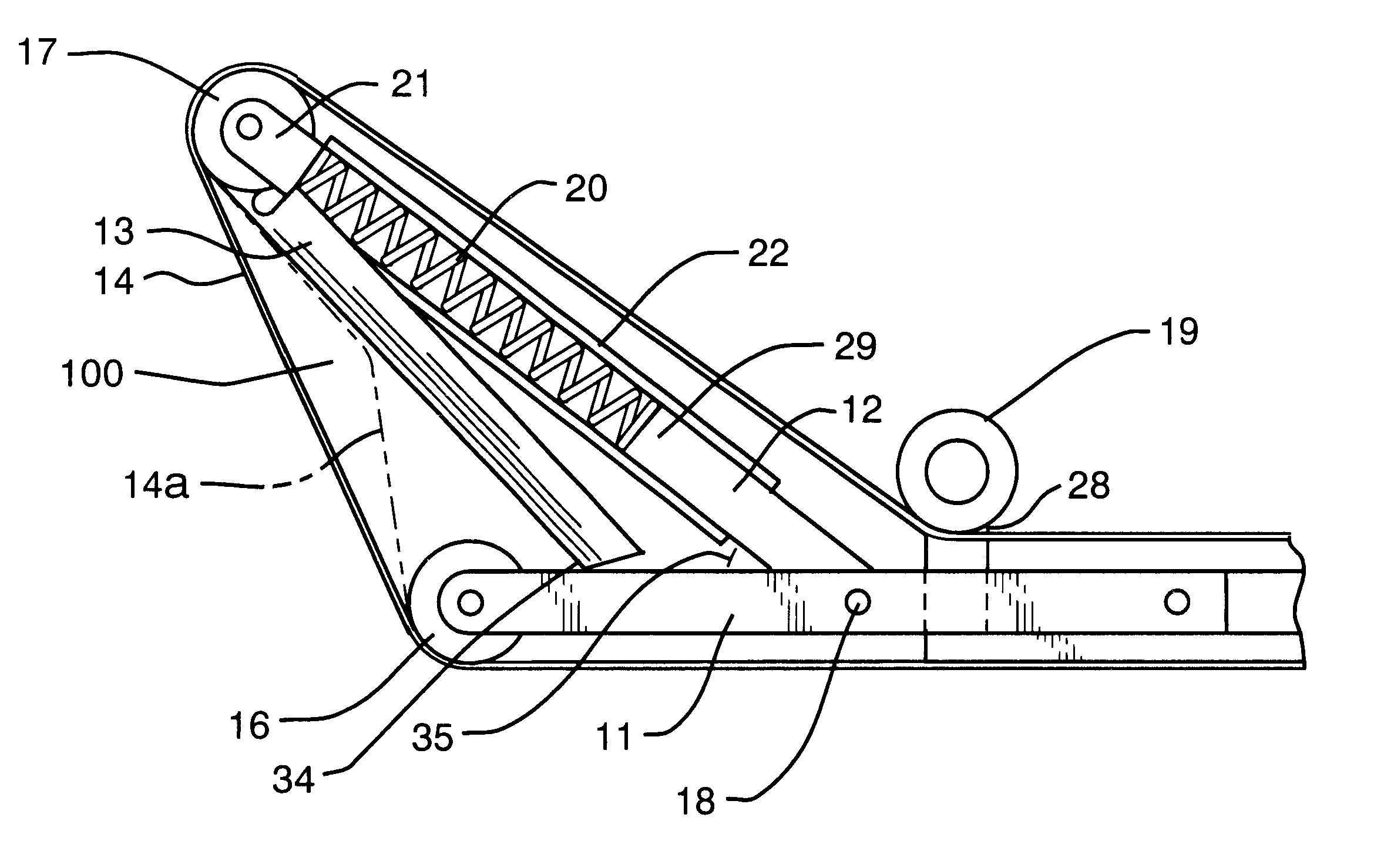
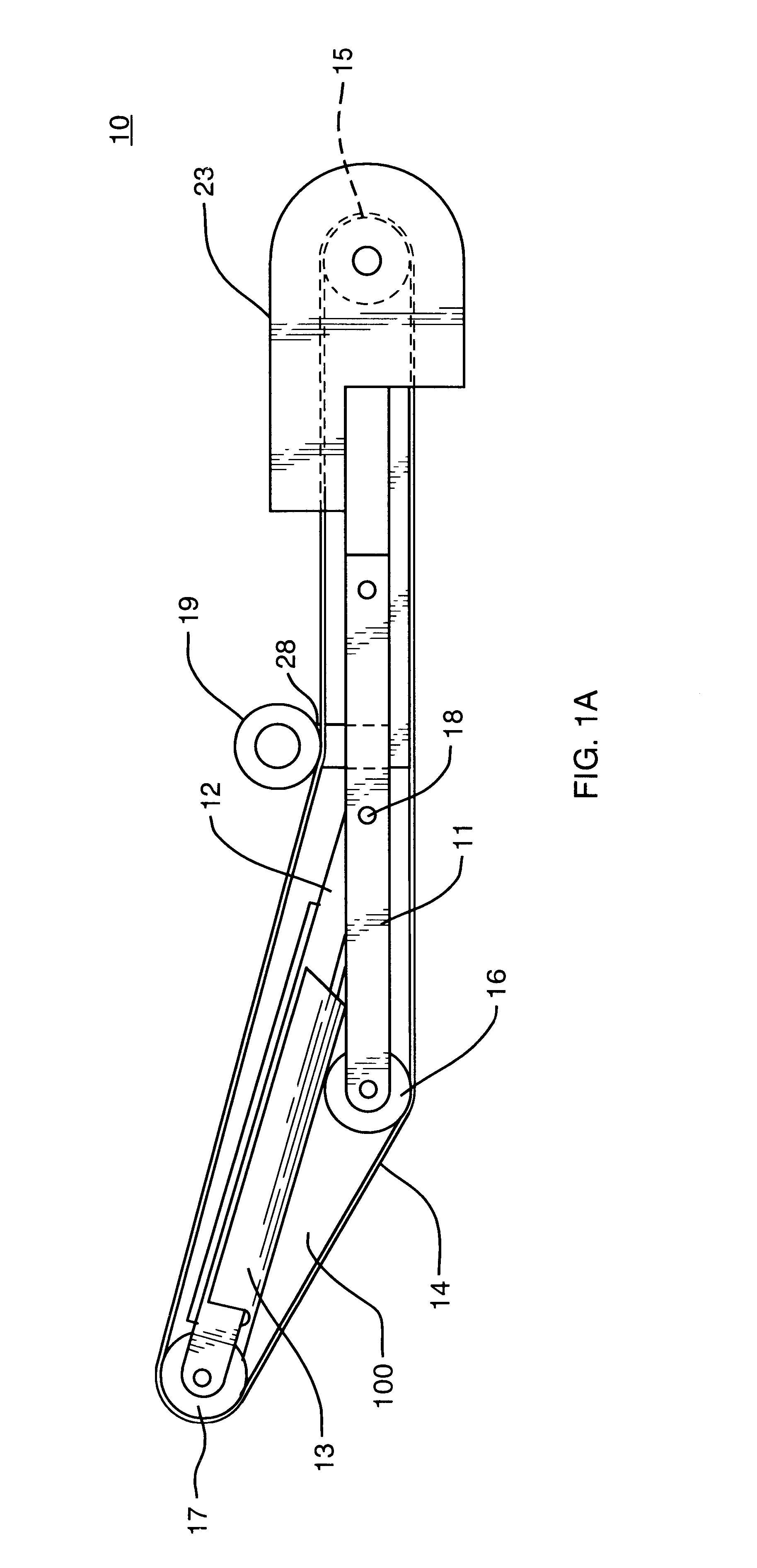
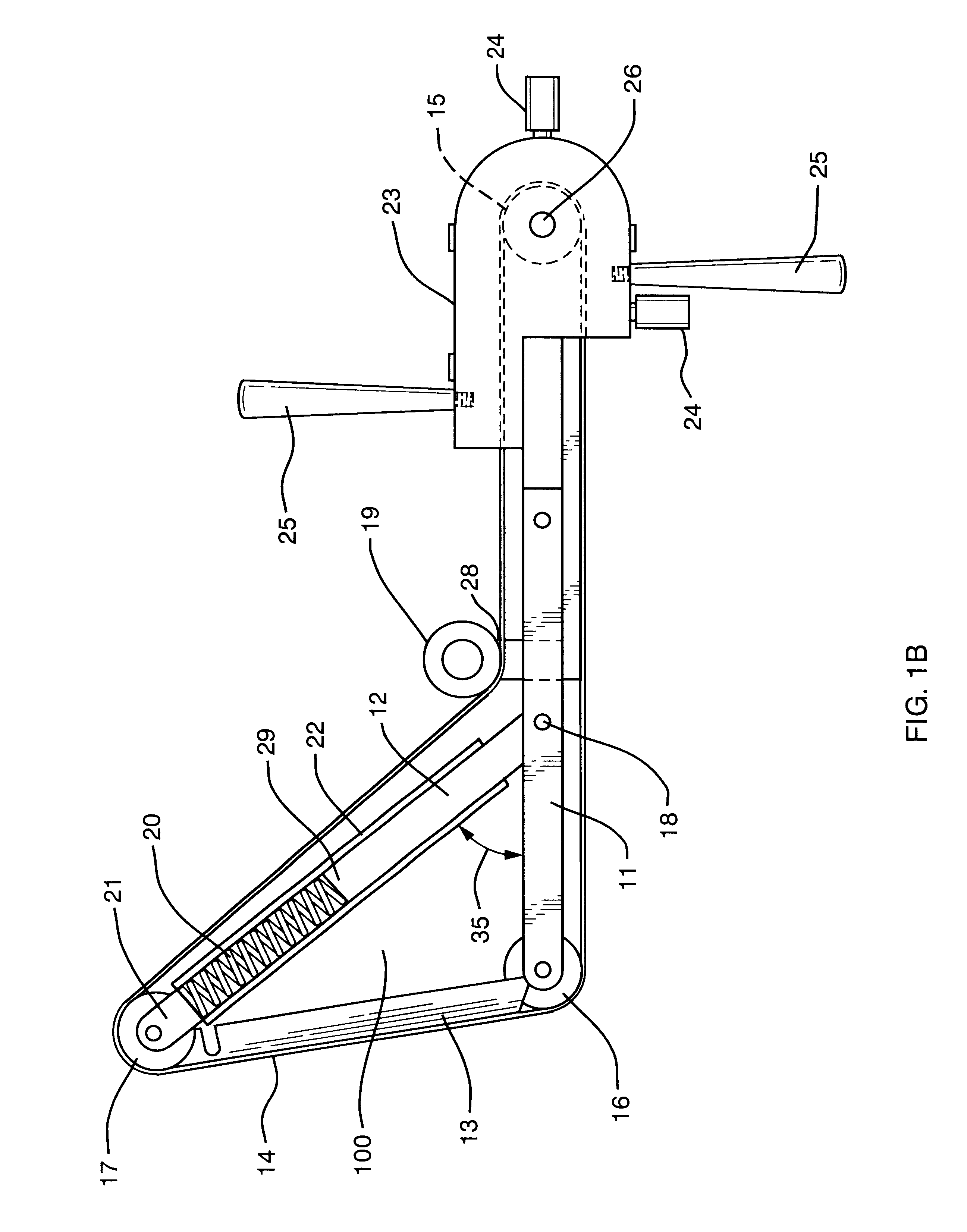
FIG. 1A, FIG. 1B and FIG. 1C show the Preferred Embodiment of the present invention--a contour-sander attachment device 10--by itself, unattached to any power tool. As shown on the right side of FIG. 1A, the device 10 includes a body 23 that houses a drive-pulley 15. It is the drive-pulley 15 that provides the motive force to a sanding belt 14 when the device 10 is in use. As shown in FIG. 2, the motive force causing the drive-pulley 15 to rotate comes from a drive axle 26 that is coupled to a chuck 31 of a power tool 30 when the device 10 is in use. As further shown in FIG. 1B, the drive axle 26 is rotatably mounted in and supported by the body 23 by means of a bearing assembly 32.
When the device 10 is in operation, the sanding belt 14--driven by the drive-pulley 15--runs around a path a portion of which, the working portion, passes over a belt-support 100, as shown in FIG. 1A and elsewhere. The belt-support 100 extends laterally from the body 23. The working portion of the path is...
PUM
| Property | Measurement | Unit |
|---|---|---|
| Fraction | aaaaa | aaaaa |
| Power | aaaaa | aaaaa |
| Flexibility | aaaaa | aaaaa |
Abstract
Description
Claims
Application Information
 - R&D
- Intellectual Property
- Life Sciences
- Materials
- Tech Scout
- Unparalleled Data Quality
- Higher Quality Content
- 60% Fewer Hallucinations
Browse by: Latest US Patents, China's latest patents, Technical Efficacy Thesaurus, Application Domain, Technology Topic, Popular Technical Reports.
© 2025 PatSnap. All rights reserved.Legal|Privacy policy|Modern Slavery Act Transparency Statement|Sitemap|About US| Contact US: help@patsnap.com


