Boring arrangement and method for boring holes in overlapping workpieces

a technology of overlapping workpieces and boring arrangements, which is applied in the direction of drilling/boring measurement devices, metal-working machine components, manufacturing tools, etc., can solve the problems of requiring considerable effort to remove or correct any such positioning inaccuracies, and the above-described assembly sequence is very work-intensiv

Inactive Publication Date: 2003-01-07
AIRBUS OPERATIONS GMBH
View PDF18 Cites 25 Cited by
  • Summary
  • Abstract
  • Description
  • Claims
  • Application Information

AI Technical Summary

Benefits of technology

The above objects have been achieved according to the invention in a boring arrangement adapted to be connected to and used together with a boring machine equipped with a boring tool such as a boring bit or drill bit, especially for boring holes in overlapping workpieces. The boring arrangement includes a first element on the boring machine side and a second element on the workpiece side. In other words, the first element is generally connected to or in contact with the boring machine, while the second element is generally in contact with the workpiece. The two elements are operatively connected and cooperate with each other so as to enable a relative motion therebetween in the boring feed advance direction. The boring arrangement further includes means for transmitting a contact force or pressing force against the workpiece. The second element on the workpiece side cooperates with a pressing sleeve that can be set onto one of the workpieces, and that has an opening such that the boring bit can be guided and moved therethrough for boring a hole into at least one of the workpieces. Moreover, the boring arrangement includes an air flow or suction arrangement for removing swarf material such as chips and dust particles from the boring site, and thereby prevents the formation of a chip jam or the accumulation of swarf in the boring arrangement as well as in the joint areas of the workpieces.
According to the invention, it is especially advantageous that no boring chips, turnings, dust, fiber residues, or other swarf particles can accumulate in the joint surfaces between the two overlapping components, because the swarf materials are contained in the pressing sleeve and then suctioned away. For this reason, the overall assembly process can omit the additional steps of separating and moving apart the two workpieces, deburring the bored holes, cleaning the joint areas, moving the two workpieces once again into the overlapping position, and tack-riveting or otherwise holding the two components together after the copy-boring of the tacking holes. Thus, the total number of work steps involved in the joining operation during the structural assembly of the workpieces, and especially during the transverse seam assembly of an aircraft fuselage, can be significantly reduced. This makes it possible to achieve shorter total assembly and throughput times in the overall manufacturing of components or structures such as an aircraft fuselage.
The above mentioned guide bolts are preferably provided with helical compression springs thereon as a simple and economical embodiment for achieving a predeterminable pressing force and providing the required operative connection between the outer and inner sleeves that form the first element and the second element, or the second element and the first element, respectively. As an alternative, a spiral spring such as a helical compression spring may be integrated into the outer sleeve element, such that this spiral spring provides the required relative motion between the outer sleeve element and the inner sleeve element, in a space saving manner that is not sensitive to fouling or contamination.
This arrangement creates an air circulation to achieve an axial transport of swarf material without allowing swarf chips or the like to escape radially outwardly out of the pressing sleeve. Thus, all of the swarf material is maintained inside the pressing sleeve, and is then sucked away by the suction arrangement. Directly in the area of the boring location, extending in a direction toward the suction pipe, a defined air channel may additionally by provided to have a cross-section matching the suction pipe, in order to prevent a so-called cyclone effect which would otherwise tend to reduce the air flow velocity and thereby cause the swarf material to settle out of the air flow. Thereby, an advantageous flushing air flow is maintained to flush the swarf material away from the boring location and into the suction pipe, where it is sucked away.

Problems solved by technology

Due to the great number of rivet holes that are necessary for the assembly of the fuselage of an aircraft, and especially a large commercial passenger aircraft, the above described assembly sequence is very work intensive.
Considerable effort is required for removing or correcting any such positioning inaccuracies that may occur.

Method used


Image

  • Boring arrangement and method for boring holes in overlapping workpieces
  • Boring arrangement and method for boring holes in overlapping workpieces
  • Boring arrangement and method for boring holes in overlapping workpieces

Examples


first embodiment

FIGS. 3A and 3B show the pressing sleeve 12 schematically on an enlarged scale. In this embodiment, the above-mentioned air openings in the pressing sleeve 12 are particularly embodied as air holes 16 extending radially through the wall of the pressing sleeve 12. The wall of the pressing sleeve 12 is rather thin, preferably with a wall thickness of about 0.1 to 0.15 mm. The air holes 16 are simple bored holes having a diameter, for example, of about 0.3 mm, and being uniformly distributed about the circumference of the pressing sleeve 12. It is also possible to provide one or more air holes directly at the edge or end surface of the pressing sleeve 12, for example in the form of notches or half-round cut-outs provided in the end surface of the sleeve 12. Particularly, the number, size, and location of the air holes 16 is selected to achieve such an air circulation so that the suction air that flows in a direction toward the suction pipe 8A entrains and transports the chips and other...

second embodiment

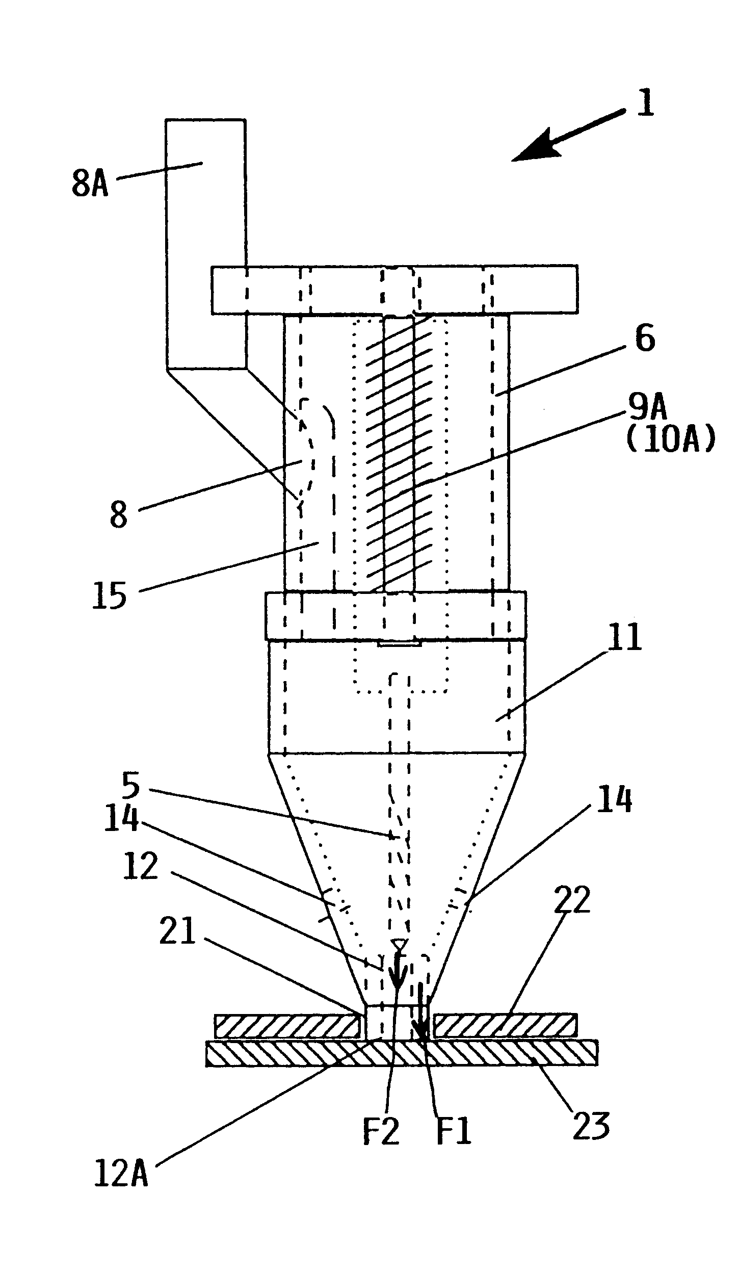
In order to prevent a chip jam or accumulation of swarf material in the boring arrangement 30, the various swarf materials are transported by means of suction air in an axial direction away from the boring site and into the chip suction pipe 38A that leads into a chip suction pipe. For this purpose, a suction channel 38 is preferably provided in the inner sleeve 32. Since the pressing sleeve 12 is tightly pressed against the workpiece around the boring site, air openings must be provided in the pressing sleeve 12 in order to provide a sufficient air circulation to support the chip transport in the suction direction, without allowing chips to emerge radially out of the pressing sleeve 12 through these air openings. Possible embodiments of such air openings in the pressing sleeve 12 have already been described above with reference to FIGS. 3 and 4, whereby such air openings also apply to this second embodiment of a boring arrangement 30. In order to further support the air circulation...


PUM

PropertyMeasurementUnit
Thicknessaaaaaaaaaa
Thicknessaaaaaaaaaa
Forceaaaaaaaaaa

Abstract

A boring arrangement is connected to a boring machine equipped with a boring bit for boring a hole in overlapping workpieces. The boring arrangement includes a first sleeve connected to the boring machine, and a second sleeve that is movably connected to the first sleeve so as to allow a relative motion therebetween in a boring feed advance direction. Biasing elements such as springs apply a biasing force between the first and second sleeves so as to exert a pressing force through the second sleeve onto a pressing sleeve connected thereto. The boring bit moves through the interior of the pressing sleeve to bore the required hole in the workpiece. Thereby, the pressing sleeve surrounds the boring site and is seated and pressed against the workpiece with a pressing force that is greater than the boring feed advance force exerted by the boring bit onto the workpiece. A suction arrangement sucks away boring chips and other swarf material arising during the boring process. Thereby, the accumulation of swarf material in the joint areas between the two overlapping workpieces is avoided, and there is no need to separate the workpieces to remove swarf material.

Description

PRIORITY CLAIMThis application is based on and claims the priority under 35 U.S.C. .sctn.119 of German Patent Application 199 49 673.0, filed on Oct. 14, 1999, and German Patent Application 100 03 647.3, filed on Jan. 28, 2000, the entire disclosures of which are incorporated herein by reference.The invention relates to a boring arrangement to be connected to a boring machine equipped with a boring tool such as a bit for boring holes, especially in overlapping workpieces. The invention further relates to a method of boring holes using such a boring arrangement.BACKGROUND INFORMATIONIn the field of aircraft construction, the assembly of various structural components is typically carried out by boring holes in the respective components and then securing the components to each other using rivets engaged in the bored holes. To carry this out, the components are typically first laid into respective contour-determining jigs or similar apparatus. The respective joint surfaces of the compon...

Claims


Application Information

Patent Timeline
IPC IPC(8): B23Q11/00B23B49/00B23B47/28B23B49/02B23B47/00
CPCB23B47/28B23B49/02B23Q11/0046Y10T408/56245Y10T409/304088Y10T408/03Y10T408/50
Inventor ENDE, WOLFGANGSCHUELER, HARALD
Owner AIRBUS OPERATIONS GMBH
Why Eureka
Try Eureka