Method and apparatus for recording an optical grating in a photosensitive medium

a technology of optical gratings and photosensitive mediums, applied in electrical apparatus, cladded optical fibres, instruments, etc., can solve the problems of spatial dependence of diffraction efficiency, deformation of optical characteristics of the resulting grating, and inflexible writing setups of typical writing setups with phase masks. , to achieve the effect of being versatile and commercially practicabl

Inactive Publication Date: 2002-12-31
TERAXION
View PDF8 Cites 13 Cited by
  • Summary
  • Abstract
  • Description
  • Claims
  • Application Information

AI Technical Summary

Benefits of technology

Accordingly, it is an object of the present invention to provide a method of recording optical gratings in a photosensitive medium that is versatile and commercially practical.
ii) providing a curvature in the light beam wavefront along the direction of the waveguiding axis, this curvature having a wavefront radius of curvature at a phase mask plane selected to generally optimize an efficiency of the recording of the optical grating for this characteristic period.
ii) providing a wavefront curvature in said light beam along the direction of the waveguiding axis, said curvature having a wavefront radius of curvature in a plane of the phase mask selected to generally optimize an efficiency of the recording of the optical grating for said characteristic period.
2) providing a curvature in said light beam along the direction of the waveguiding axis, said curvature having a wavefront radius of curvature in a plane of the phase mask selected to generally optimize an efficiency of the recording of the optical grating for said characteristic period.
Advantageously, the present invention allows to locally control the period of an optical grating over a large range (about .+-.2% of the nominal period) while keeping the optical quality of the grating unaffected. Other techniques have been proposed but result in a degradation of the optical performances.

Problems solved by technology

However, a typical writing setup with a phase mask is not flexible and allows the fabrication of only one type of fiber Bragg gratings, that is, the one with the specifications prescribed by the phase mask.
However, the optical characteristics of the resulting grating are degraded: the photo-induced grating is slanted (blazed) in a spatially-dependent manner.
Such a slanted fringes inside the grating causes a spatial dependence of the diffraction efficiency and increases significantly the polarization dependent loss and polarization mode dispersion.
Another drawback is the need for uncommonly large lenses when a long grating is to be photo-induced, making the method more costly and unpractical.

Method used


Image

  • Method and apparatus for recording an optical grating in a photosensitive medium
  • Method and apparatus for recording an optical grating in a photosensitive medium
  • Method and apparatus for recording an optical grating in a photosensitive medium

Examples


Embodiment Construction

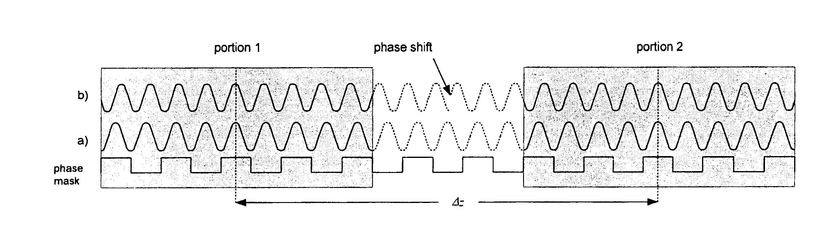
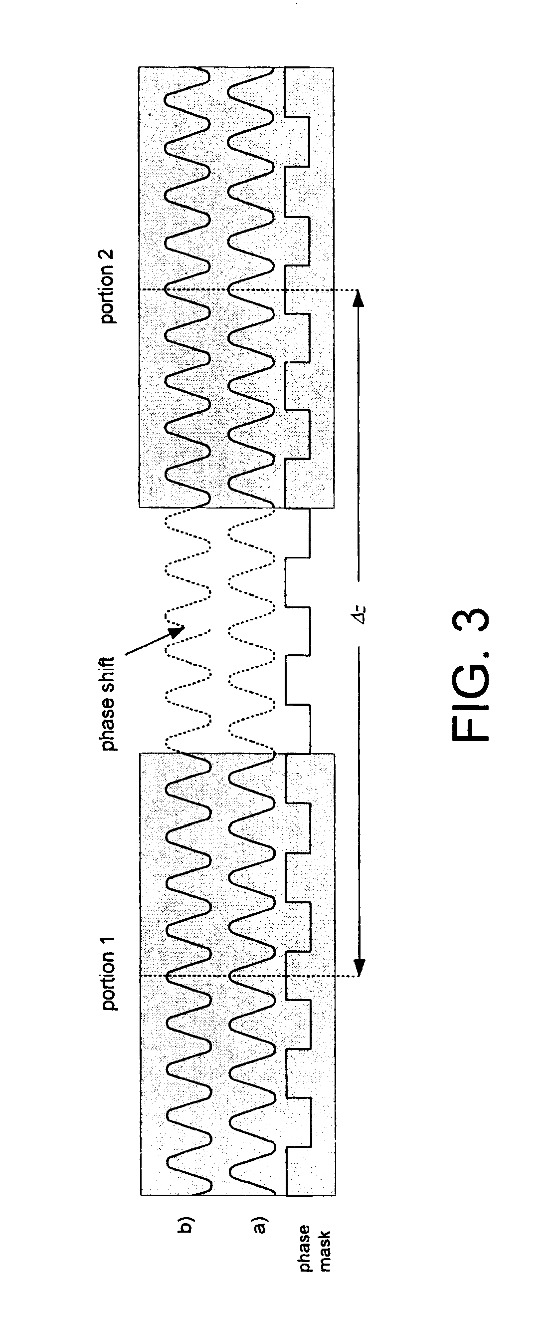
The present invention advantageously allows to improve the range of the phase mask moving technique disclosed by Cole et al. where the phase mask (or photosensitive medium) is displaced parallel to the scanning of the light beam.

In accordance with a first preferred embodiment of the invention, there is provided a method for recording an optical grating along a waveguiding axis in a photosensitive medium. Preferably, the photosensitive medium is a length of optical fiber, but any other type of waveguide where a refractive index grating needs to be written would be equally covered by the present invention. The expression "optical grating" refers generally to a periodic (or nearly periodic) refractive index change in an optical medium. It can be of any length allowed by the geometry of the system, and if desired it may be chirped, apodised, etc.

The method first involves providing a phase mask proximate the photosensitive medium, along its waveguiding axis. The phase mask preferably has...


PUM


Abstract

A method and an apparatus for recording optical gratings in a photosensitive medium are provided. The invention uses a phase mask in combination with a scanning of the recording light beam. The phase mask, or alternatively the photosensitive medium, is translated along a direction parallel to the scanning of the light beam, so that the period of the recorded grating may be locally adjusted. To ensure a proper recording efficiency over a large range, an appropriately selected wavefront curvature is provided in the light beam. The method of the invention is particularly advantageous for the recording of superimposed grating components in a photosensitive medium.

Description

The present invention relates to the field of components for optical telecommunications and more particularly concerns a method and a corresponding apparatus for recording optical gratings in a photosensitive medium with an enhanced control of the characteristics of the grating.Phase masks are widely used for the fabrication of UV-induced fiber Bragg gratings since their first reports (see for example K. O. Hill, B. Malo, F. Bilodeau, D. C. Johnson, and J. Albert, "Bragg gratings fabricated in monomode photosensitive optical fiber by UV exposure through a phase mask" Appl. Phys. Lett., pp.1035-1037 (1993); U.S. Pat. No. 5,367,588 (Hill et al.); D. Z. Anderson, V. Mizrahi, T. Erdogan, and A. E. White, "Production of in-fibre gratings using a diffractive optical element" Electron. Lett., pp.566-568 (1993); and U.S. Pat. No. 5,327,515 (Anderson et al.). The use of such a diffractive element renders easy the mass production of fiber Bragg gratings as the mask acts somewhat as a master r...

Claims


Application Information

Patent Timeline
IPC IPC(8): G02B6/02G02B6/124G02B6/34G02B6/12
CPCG02B6/02138G02B6/02152G02B6/124G02B6/02085G02B2006/12173
Inventor PAINCHAUD, YVESMAILLOUX, ALAINCHOTARD, HELENE
Owner TERAXION
Why Eureka
Try Eureka