
U-shape and/or nozzle u-loop fermentor and method of carrying out a fermentation process

a technology of u-loop fermentor and nozzle, which is applied in the direction of biochemistry apparatus and processes, biochemistry apparatus, microorganisms, etc., can solve the problems of significant heating of fermentation liquid, difficult to obtain the same homogeneous mixing, and reactor type that is not particularly suitable for up-scaling

Inactive Publication Date: 2002-12-10
UNIBIO AS
View PDF4 Cites 44 Cited by
  • Summary
  • Abstract
  • Description
  • Claims
  • Application Information

AI Technical Summary

Problems solved by technology

This type of reactor is, however, not particularly appropriate for up-scaling, since it is difficult to obtain the same homogeneous mixing and the same mass transportation in large reactors as can be obtained in small laboratory and pilot reactors.
Besides, the vigorous mixing implies a significant heating of the fermentation liquid.
Furthermore, airlift reactors have a relatively poor exploitation of the injected gas.
Besides, it is difficult to obtain good and quick release of the gas bubbles from the fermentation liquid at the top of the reactor and separation of the gas phase thus produced (which may be rather foaming) from the liquid phase before the fermentation liquid moves down in the downstream part of the reactor.
Long residence time and thus high degree of exploitation of the injected gas
However, contradictory to conventional loop reactors the liquid circulation is effected by means of one or more in-line pumps.
Furthermore, the U-shape reactor provides for a long contact time between the gas and liquid phases, as the injected gas is present both in the downstream and in the upstream parts of the loop.
This tendency contributes to making conventional airlift reactors ineffective inasmuch as the bubbles become larger and larger upward through the upstream part, partly due to coalescence and partly due to a reduced hydrostatic pressure.
The drawback of the prior art U-shape and / or nozzle-U-loop fermentors in connection with the above mentioned production processes with methanotrophic bacteria and corresponding processes, wherein different gases are to be continuously supplied, which partly may be expensive and partly may constitute a potential danger of explosion if they accumulate in major amounts in the reactor, is that up to now it has been difficult or even impossible to supply these gases as well as the additional nutrients (ammonium, phosphate and minerals) necessary for the fermentation process, and pH controlling means in such amounts and relative ratios that it has been possible to obtain an optimum utilization of the gases before the separation off in the headspace of the reactor with simultaneous achievement of an optimally proceeding fermentation process providing the largest possible yield of fermentation product in the shortest possible time.
The fermentation processes are, however, biological processes which proceed far from uniformly from time to time, but are subjected to even very large variations for which reason the time-schedule fixed doses will not correspond to the actual need for attainment of the results aimed at with respect to the optimum utilization of the gases before the separation thereof in the headspace of the reactor and attainment of the largest possible yield of fermentation product in the shortest possible time.

Method used


Image

  • U-shape and/or nozzle u-loop fermentor and method of carrying out a fermentation process
  • U-shape and/or nozzle u-loop fermentor and method of carrying out a fermentation process

Examples


example of

Production

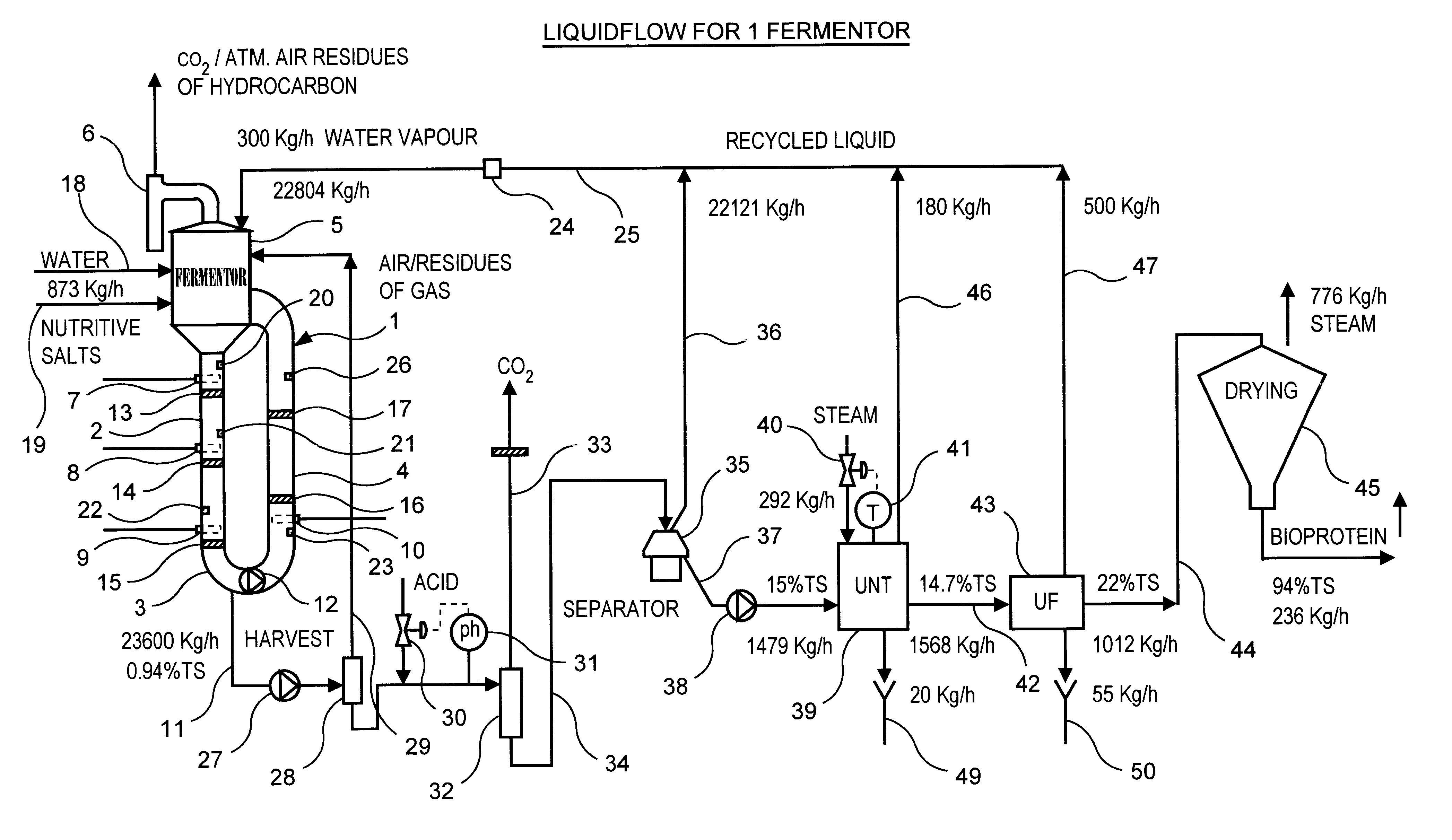
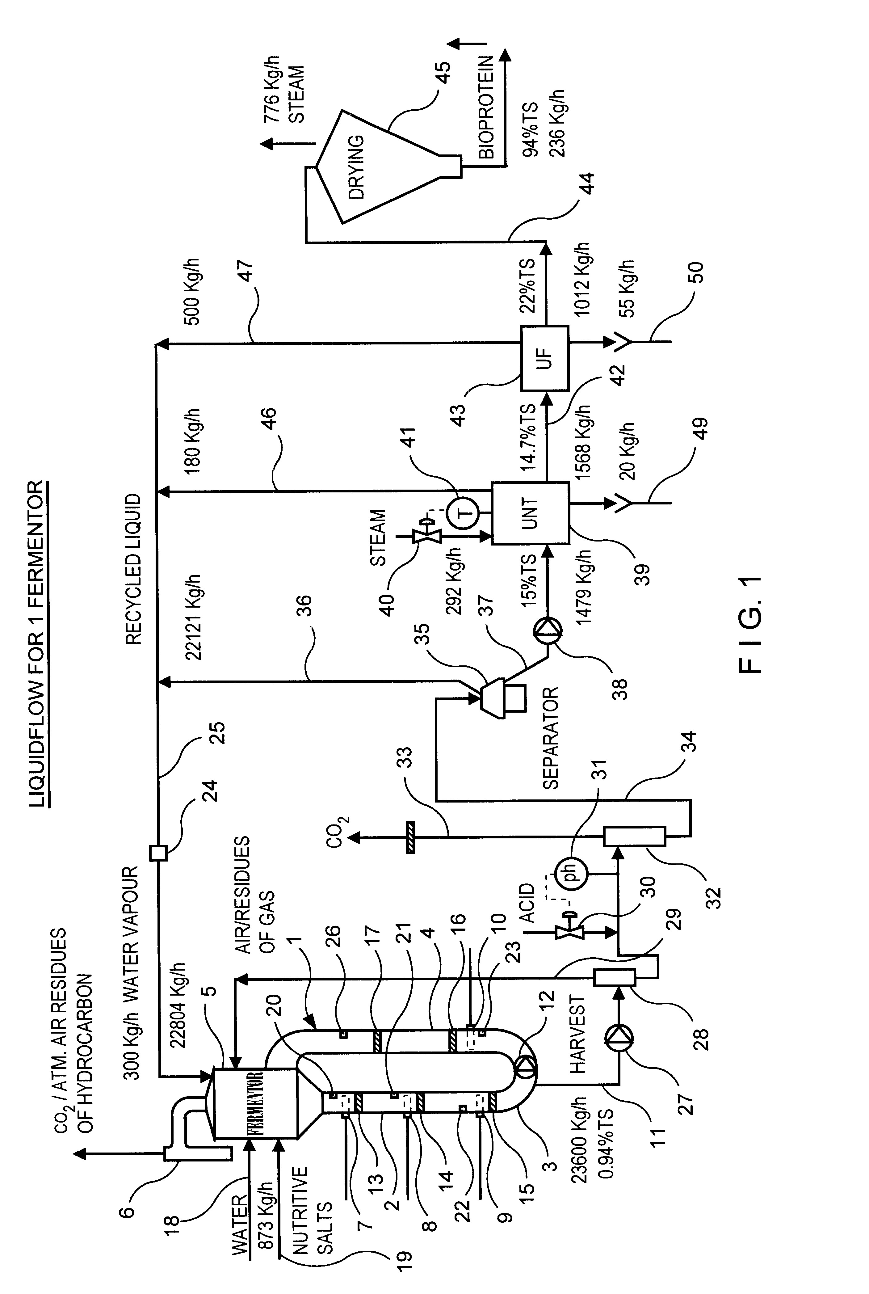
As an example of the application of the fermentor described above with accompanying process auxiliary units, a production of single cell protein using natural gas as carbon and energy sources will be described in the following.

Initially, the fermentation system is cleaned with hot sodium hydroxide followed by a short treatment with dilute nitric acid solution and sterilization with super heated steam having a temperature of 120.degree. C. for one hour. The fermentor is then filled with water , which has been heat-sterilized at 130.degree. C. for 10 seconds. Gases and solutions of minerals, ammonia and phosphoric acid are also sterilized before they are fed into the fermentor.

Atmospheric air, pure oxygen or atmospheric air enriched with pure oxygen is used as oxygen source and ammonia is used as nitrogen-source. Additionally, phosphate is introduced as phosphoric acid and minerals, such as magnesium, calcium, potassium, iron, copper, zinc, manganese, nickel, cobalt and moly...


PUM


Abstract

A U-shape and / or nozzle-U-loop fermentor has a U-part consisting of an essentially vertical downstream part (2), an essentially vertical upstream part (4), a U-shape bend part (3) which connects the lower ends of the downstream and upstream parts, an inline pump (12) placed in the U-part for circulation of fermentation liquid in the fermentor, a top part (5) which is placed above the upper end of the downstream part, gas supply members (7, 8, 9, 10) which are provided in the U-part with appending static-mechanical mixing members (13, 14, 15, 16, 17) for the comminution of the gases introduced into the fermentation liquid, and supply numbers for water and nutrient salts (18) and (19), respectively, and in connection with the supply members (7, 8, 9, 10, 18, 19) or in by-pass arrangements in connection therewith one (or more) ion sensor(s) or analyser(s) (20, 21, 22, 23) for sensing the concentration of at least one of the ion species phosphate, ammonium, nitrate and hydrogen ion, oxygen sensor(s) for sensing the oxygen concentration, and at least one thermo phial for sensing the temperature, said sensor(s), analyser(s) and phial(s) delivering signals to a data processing system (PC), wherein the signals received are processed and the dosage of feed gases, water, minerals and pH adjustment means via the supply members (7, 8, 9, 10, 18, 19) are calculated and optimised from pre-programmed amounts relative to the results measured.

Description

In its broadest aspect the present invention relates to U-shape and / or nozzle-U-loop fermentors and methods of the operation of the same.More specifically the invention relates to U-shape and / or nozzle-U-loop fermentors and methods for the operation of the same, which are particularly appropriate for production processes with methanotrophic bacteria and similar processes, whereby different gases and other nutrients are to be supplied to the fermentation liquid in order to obtain an optimally proceeding fermentation process with the highest possible yield of fermentation product in the shortest possible period of time.PRIOR ARTStirred Or Back-mix FermentorsIn conventional bioreactors (fermentors) the mixing of gases with the fermentation liquid is effected by means of stirrer blades placed centrally in the fermentor. The stirrer blades generate turbulence in the liquid, which means that gas, usually injected at the bottom of the reactor, will be dissipated in the liquid in the form o...

Claims


Application Information

Patent Timeline
IPC IPC(8): C12M1/38C12M1/36
CPCC12M29/18C12M41/32C12M41/48Y10S435/813C12M29/02C12M29/24C12M41/26C12M47/10C12M47/14C12M47/16
Inventor LARSEN
Owner UNIBIO AS
Learn More