
Humidity chamber for scanning stylus atomic force microscope with cantilever tracking

a technology of atomic force microscope and humidity chamber, which is applied in the direction of mechanical measurement arrangement, mechanical roughness/irregularity measurement, instruments, etc., can solve the problems of surface contamination, current commercially available humidity chamber, limited to scanned sample afm,

Inactive Publication Date: 2002-12-10
COMMERCE UNITED STATES OF AMERICA AS REPRESENTED BY THE SEC OF THE
View PDF31 Cites 8 Cited by
  • Summary
  • Abstract
  • Description
  • Claims
  • Application Information

AI Technical Summary

Benefits of technology

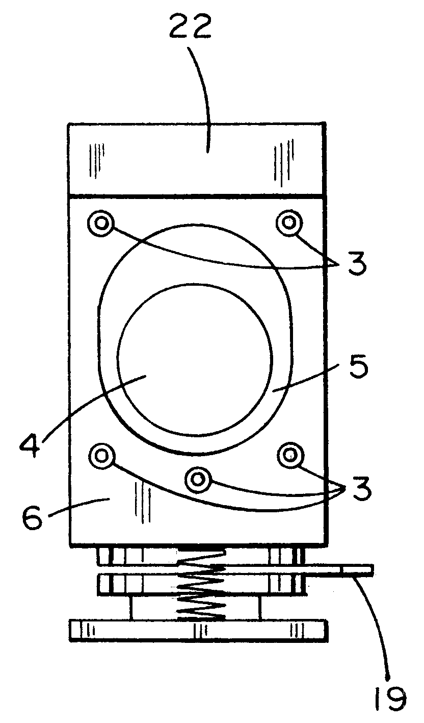
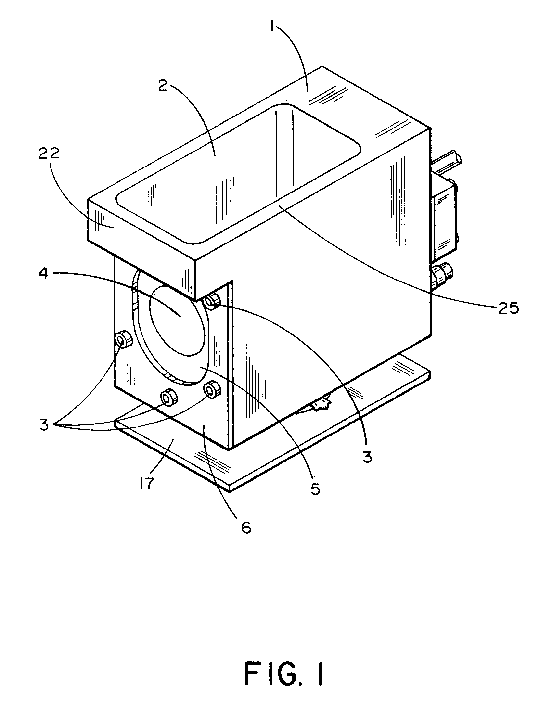
It is a further object of the present invention to provide a humidity chamber suitable for use with a scanned stylus AFM which also provides for full enclosure of one or more of the AFM scanner, tip assembly, optical lever detection system, sample, and side-mounted optical microscope objective lens (camera), without degrading the ability to operate the AFM or the related systems.
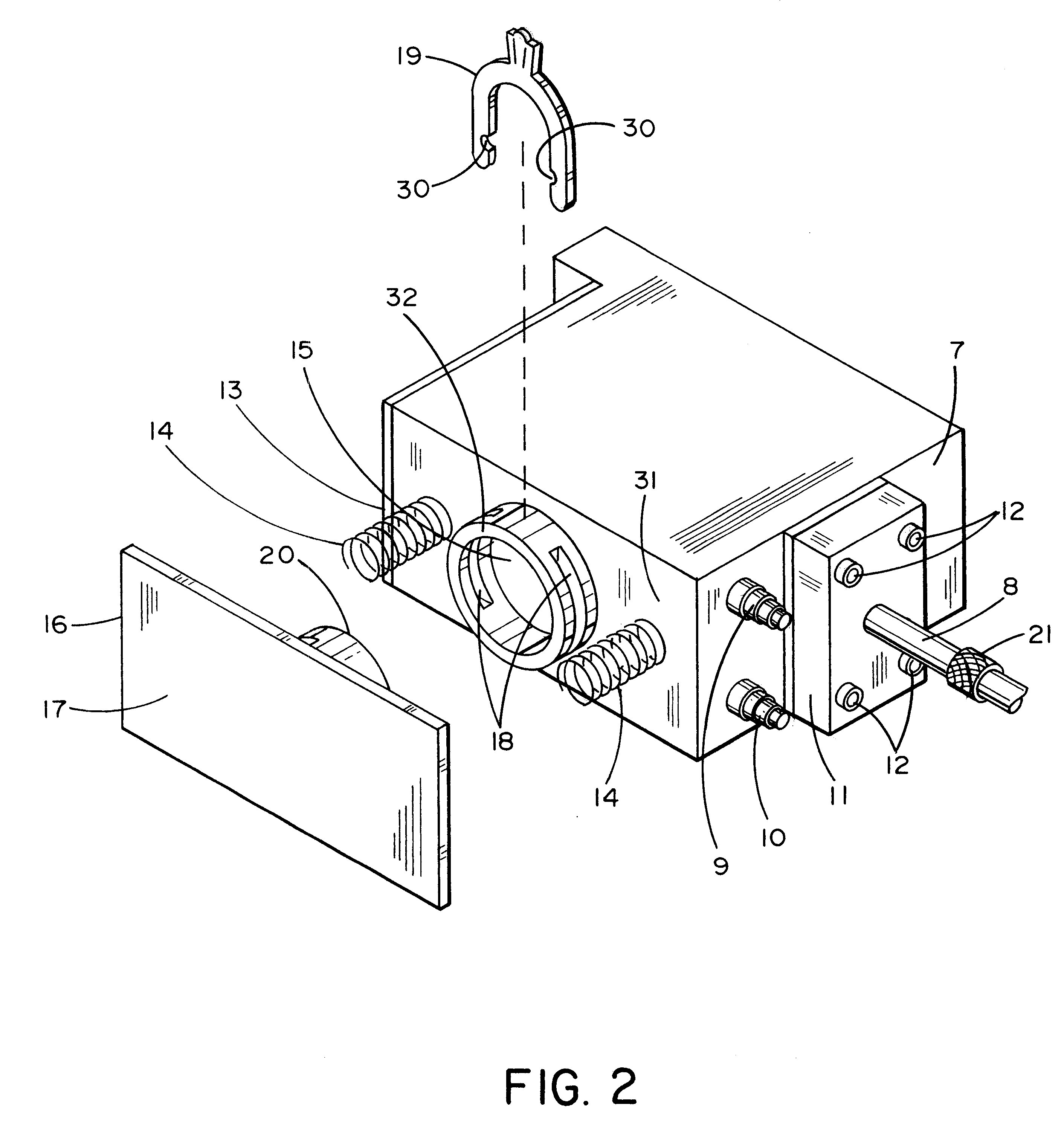
The use of chamber walls 25 which are thicker than those shown in the preferred embodiment is within the scope of the present invention and in fact may be preferable in that thicker walls will better insulate the chamber, which may be desirable. Alternatively, insulation can be achieved by the use of heat pads, or a heating element, applied to the chamber (not shown). For instance, in situation where a heated environment is desired, warm air with a controlled relative humidity percentage (if desired), can be blown into the chamber through the conditioned air input 9 port, and in order to avoid condensation, the chamber can be maintained at the same temperature by the application of heating pads, or heating elements, to the outside of the chamber.

Problems solved by technology

However, during imaging in ambient conditions, surface contamination will occur due to the presence of moisture in the form of humidity that will adsorb onto the sample surface.
The existing commercially available humidity chamber, however, is limited to a particular type of scanned sample AFMs, where the AFM probe and detection system are fixed and the sample is moved by the scanners.
Thus, the currently available humidity chamber is limited to scanned sample AFMs and cannot be used with scanned stylus AFMs, where the sample is fixed and the probe is rastered across the sample by the scanners.
The head of the scanned stylus AFM has a much more complicated geometric design than the scanned sample AFM, thus rendering the design of a humidity chamber a much more difficult task.

Method used


Image

  • Humidity chamber for scanning stylus atomic force microscope with cantilever tracking
  • Humidity chamber for scanning stylus atomic force microscope with cantilever tracking
  • Humidity chamber for scanning stylus atomic force microscope with cantilever tracking

Examples


Embodiment Construction

FIGS. 7-11 provide the precise dimensions of an embodiment of the humidity chamber configured to accommodate a scanned-stylus AFM such as that manufactured by Digital Instruments, or as described in U.S. Pat. Nos. 6,032,518; 5,714,682; 5,560,244; and 5,463,897. In FIG. 7, a hole in the front of the chamber is shown which accommodates the particular optical system used on a current commercially available scanned stylus AFM similar to that described in the aforementioned U.S. Patents. This particular optical system contains a camera with an objective lens that is positioned at an angle approximately 15.degree. from the horizontal plane. Note that the hole in the chamber has a larger diameter than the camera lens. To seal the chamber around the lens, a 2 mm thick piece of silicon rubber (not shown) is mounted on the front of the chamber with the securing plate shown in FIG. 11. The securing plate has a hole with dimensions larger than the camera lens, but the diameter of the hole in th...


PUM

PropertyMeasurementUnit
angleaaaaaaaaaa
thickaaaaaaaaaa
humidityaaaaaaaaaa

Abstract

The present invention provides a novel humidity chamber suitable for use with an atomic force microscope (AFM). The humidity chamber of the present invention employs an intricate geometrical design which can accommodate a scanned-stylus AFM with an optical lever. This geometrical design allows the invention to enclose one or more of the AFM scanner, tip assembly, optical lever detection system, sample and an optical microscope objective lens, without degrading the ability to operate the AFM or the related systems. The invention is comprised of two major pieces: a chamber within which the AFM scanning head assembly is placed, and an integrated sample platform and spring-loaded base-plate that allows samples to be loaded and unloaded without removal of the chamber from the AFM scanning head assembly. The sample platform, which extends up from the base-plate and is inserted into the chamber, can include a magnet that is securely attached to the base. Once the sample platform is positioned inside the chamber, a locking pin can be inserted between the chamber and the bottom portion of the sample platform to secure the sample platform and base-plate. The spring-loaded base allows the z-directional motors of the AFM to be used to position the sample just below the probe prior to scanning, while at the same time providing an essentially air-tight fit between the chamber and the AFM scanning head. An embodiment of the present invention is suitable for use with components that sense and control the relative humidity inside the chamber.

Description

The present invention relates to environmental control for atomic force microscopes, and in particular to controlling the humidity level of the environment local to the probe and sample during scanning with a scanning stylus atomic force microscope.The Atomic Force Microscope, or AFM, allows high-resolution imaging at the subnanometer level, and in a liquid environment at the atomic level. The basic objective of the operation of the AFM is to measure the forces (at the atomic level) between a sharp probing tip (which is attached to a cantilever spring) and a sample surface. Images are taken by scanning the sample relative to the probing tip and measuring the deflection of the cantilever as a function of lateral position. The AFM probe is scanned across the sample surface to generate an image. As the scan progresses the AFM measures the small upward and downward movements that are needed to maintain a constant force of contact. Because the AFM senses the surface by "touch", it allows...

Claims


Application Information

Patent Timeline
Patent Type & Authority Patents(United States)
IPC IPC(8): G12B21/00G12B21/22G01N35/00G01Q30/02G01Q30/08G01Q30/14
CPCB82Y35/00G01Q30/14G01N2035/00455Y10S977/871
Inventor MARTIN, JONATHAN W.EMBREE, EDWARDVANLANDINGHAM, MARK R.
Owner COMMERCE UNITED STATES OF AMERICA AS REPRESENTED BY THE SEC OF THE
Learn More