
Multi-battery fuel saving and emission reduction system for automotive vehicles

a multi-battery, emission reduction technology, applied in the direction of machines/engines, process and machine control, fluid pressure control, etc., can solve the problems of consuming a correspondingly greater amount of fuel, vehicle engine and alternator substantially less than 100% efficiency, and consuming a large amount of fuel. , to achieve the effect of increasing the resistance to rotation of the alternator rotor coil, increasing the control current of the alternator rotor, and rapid increase of the charge of the battery

Inactive Publication Date: 2002-10-15
BRADLEY CHARLES W
View PDF52 Cites 59 Cited by
  • Summary
  • Abstract
  • Description
  • Claims
  • Application Information

AI Technical Summary

Benefits of technology

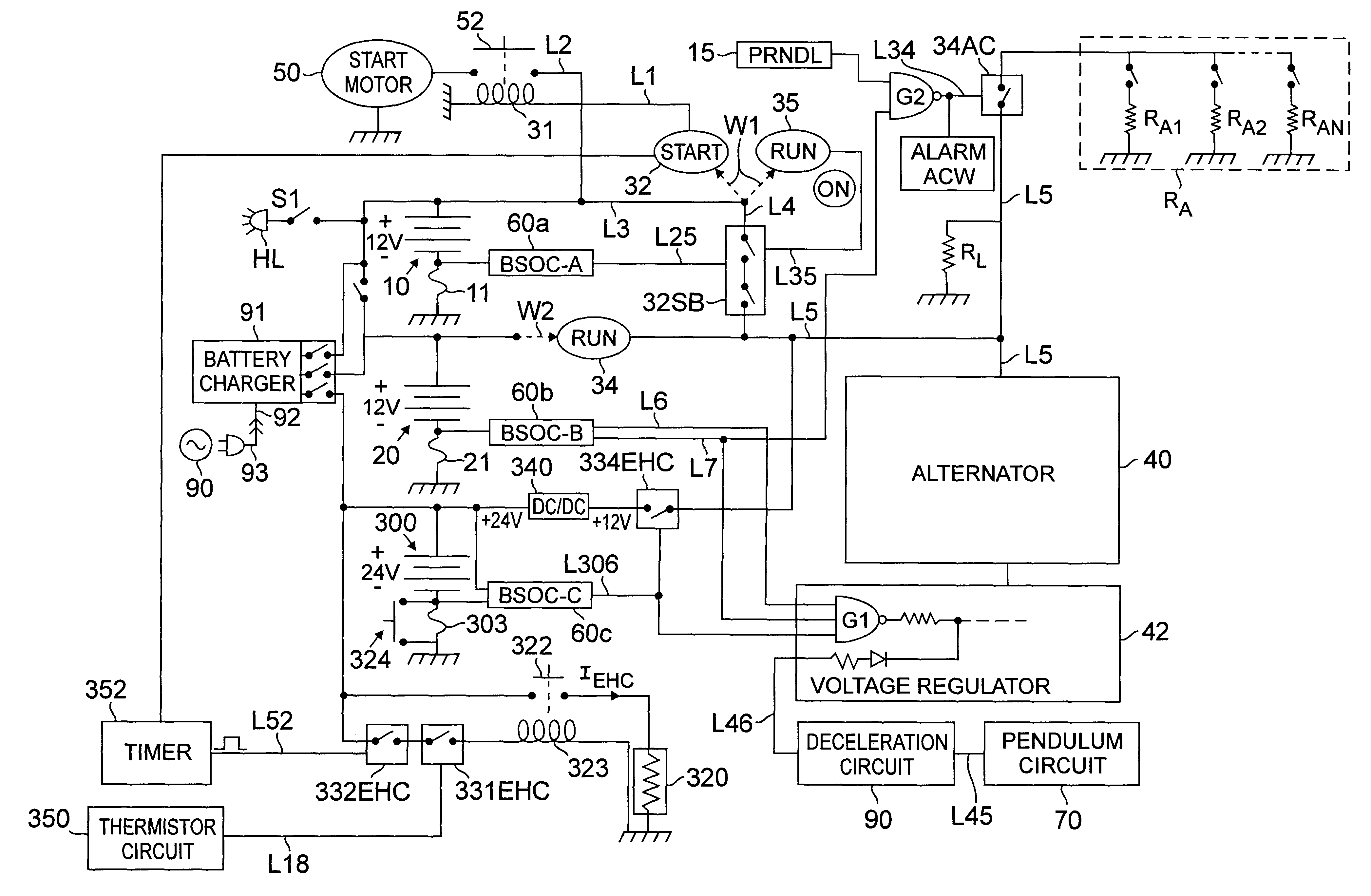
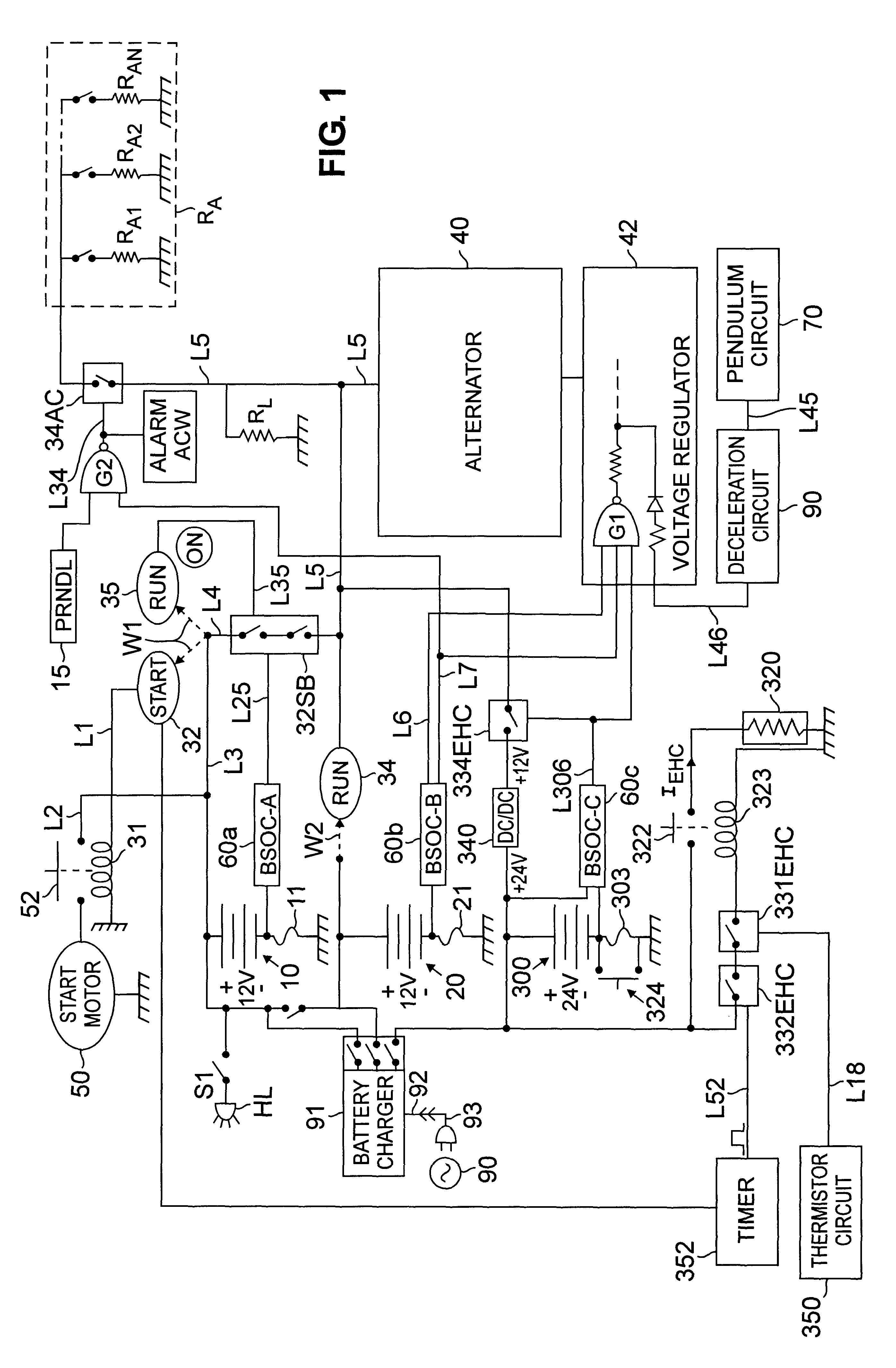
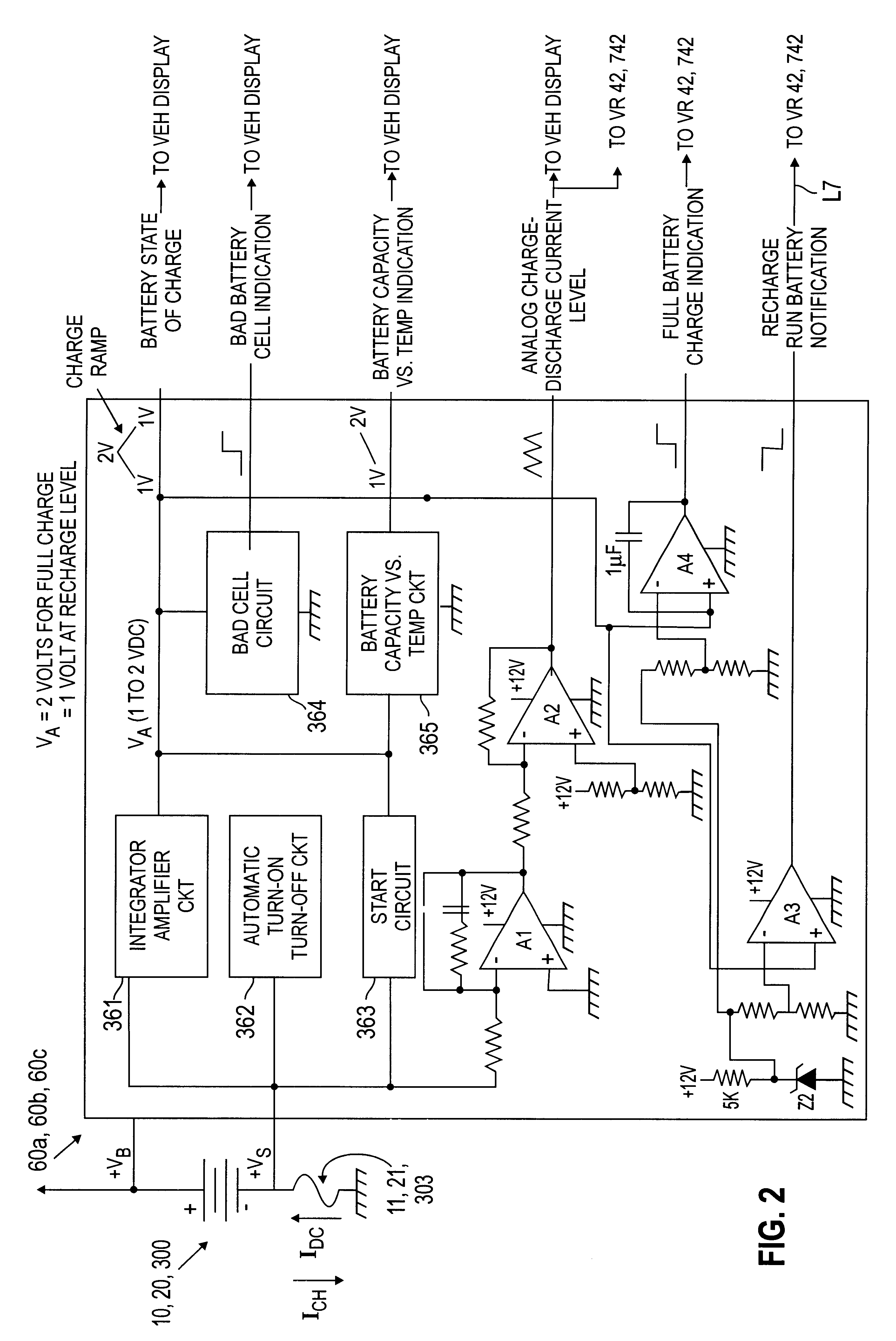
In addition, the inventor has realized that if the state of charge of the vehicle batteries are reliably and accurately determinable over their useful life it is possible to control the alternator output voltage, as required, either to charge the vehicle batteries or to allow one or more batteries to provide all the current required by the vehicle loads.
The voltage regulator circuit 42 described above is disabled by reducing the base voltage of transistor Q606 to zero. This occurs when all the inputs to NAND gate G1 are in a high state and the input on line L46 is a low state. This set of conditions causes the output of NAND gate G1 to switch to the low state and turn transistor Q606 on. When transistor Q606 switches on it reduces the voltage level on line L606 to the non-inverting input of amplifier 6A1 to zero. This prevents amplifier 6A1 from turning voltage regulator 42 on.

Problems solved by technology

Second, the vehicle electronic circuits contain power consuming voltage regulator circuits that reduce the alternator output voltage to a 12 or 5 volt level.
The fuel consumed by the engine to overcome the alternator counter torque is an unnecessary expense.
Fourth, the vehicle engine and alternator are substantially less than 100% efficient and consume a correspondingly greater amount of fuel.

Method used


Image

  • Multi-battery fuel saving and emission reduction system for automotive vehicles
  • Multi-battery fuel saving and emission reduction system for automotive vehicles
  • Multi-battery fuel saving and emission reduction system for automotive vehicles

Examples


examples

The advantages of the present invention are illustrated with reference to the fuel consumption test drives made with a 1988 General Motors Oldsmobile Cutlass, shown in FIG. 8, and a 1984 Ford Mercury Lynx, shown in FIG. 9.

All fuel measurements were made based on two-hour runs, under the weather conditions described below and the load currents on the alternator specified. Plot 8A represents highway driving in warm and dry road conditions. Plot 8B represents a combination of city and highway driving in light to heavy traffic and cool and raining road conditions. Plot 8C represents suburban driving in cool and dry road conditions. Plot 8D represents city driving in cool and dry road conditions. Plot 8E represents city driving in heavy traffic in cool and dry road conditions. Plot 9A represents highway driving. Plot 9B represents suburban driving in light traffic. Plot 9C represents suburban driving in heavy traffic. Plot 9D represents city driving in heavy traffic. For highway traffic,...


PUM

PropertyMeasurementUnit
time periodaaaaaaaaaa
start currentsaaaaaaaaaa
charging voltageaaaaaaaaaa

Abstract

A multi-battery charging system for reduced fuel consumption and emissions for an automotive vehicle. The system starts the vehicle with a start battery in a fuel savings manner, removing electrical torque from the alternator shaft, and allows a second (run) battery to provide all or some of the current required by the vehicle loads as a fuel savings measure. The system also utilizes an electrically heated catalytic converter (EHC) and a third (EHC or storage) battery to provide a 3 to 15 second preheat and / or a 20 second current, during vehicle start, to the EHC heater coil, e.g., of a small EHC located in series with a standard catalytic converter for emissions reduction to reduce emissions during start. The start battery is recharged after start and switched out of the system fully charged for future vehicle starts. The run battery is recharged when its charge level drops below a predetermined level with an on board battery charging device powered from a 115 volt or 220 volt ac power line source external to the vehicle.

Description

This invention relates to a multi-battery operating system for automotive vehicles that provides improved fuel economy and reduced emissions during operation and during starting, more particularly a three battery system having a start battery for starting the vehicle, a run battery for providing the vehicle load and accessory current, and a storage battery for preheating a catalytic converter during starting.In the normal operation of an automotive vehicle, a fully charged six cell battery having between 2.05 and 2.1 volts per cell (hereinafter referred to as a "start" battery) is used to start the engine and to operate accessory loads when the engine is not running. The conventional start battery is well suited to provide large start currents to the start motor on the order of 150 to 250 amperes.The start battery is provided with thin plates between its individual cells that provides for a rapid, large current, shallow discharge during vehicle start. Unfortunately, the start batter...

Claims


Application Information

Patent Timeline
Patent Type & Authority Patents(United States)
IPC IPC(8): G01R31/36H02J7/14G01R31/00
CPCB60L11/1861B60L11/1868G01R31/3606G01R31/3613H02J7/1423H02J7/1453H02J7/1461G01R31/006Y02T10/7005Y02T10/7044Y02T10/7066Y10S320/21Y10S320/10G01R31/3832G01R31/382B60L58/12B60L58/20H02J7/007192Y02T10/70H02J7/0049
Inventor ROGERS, WESLEY A.
Owner BRADLEY CHARLES W
Learn More