
On-site analyzer having spark emission spectrometer with even-wearing electrodes

a technology of spark emission spectrometer and analyzer, which is applied in the direction of spectrometry/spectrophotometry/monochromator, optical radiation measurement, instruments, etc., can solve the problems of further deterioration of internal parts, chemical problems, and further deterioration of non-metallic components,

Inactive Publication Date: 2002-09-24
SPECTRO SCI INC
View PDF0 Cites 35 Cited by
  • Summary
  • Abstract
  • Description
  • Claims
  • Application Information

AI Technical Summary

Benefits of technology

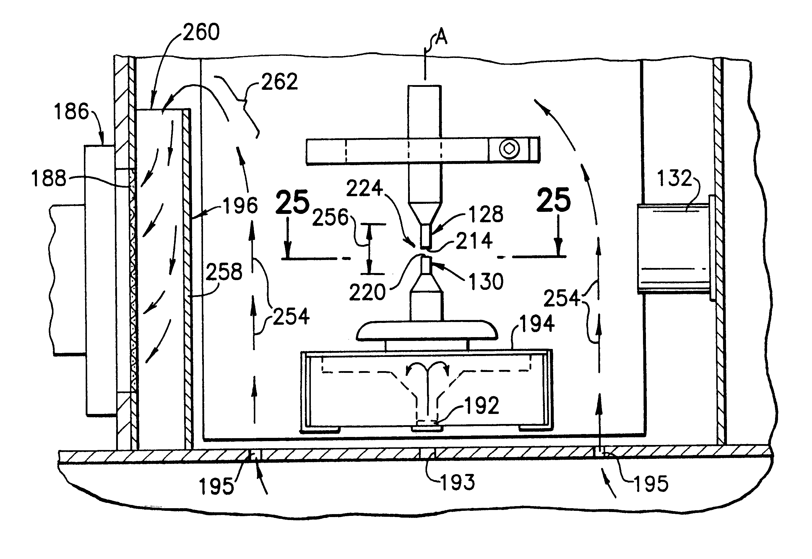
In accordance with the invention, the enclosure includes an airflow passage having a first region characterized by airflow that is substantially parallel to the longitudinal axis when the exhaust assembly is operated and the enclosure is in the closed position. The spark surfaces are contained in the first region whereby the spark electrodes wear evenly improving spectral measurements.

Problems solved by technology

For example, metal particulates may be formed through abrasion or chemical corrosion and cause further deterioration of internal parts.
In addition, normal operation causes oxidation, nitration and sulfation of the oil, altering a desired chemistry thereof.
Further, leaks between the cooling systems and the lubricating system may cause coolant (mixtures of water, ethylene glycol and other coolant chemicals) to be introduced into the oil.
For example, non-metallic components, such as pump diaphragms, gaskets and seals, fluid lines and the like, may be further affected.
Moreover, contaminants in the oil, such as ethylene glycol, fuel, silicone, water, soot and other chemicals may also present concerns.
Although PMTs in the manner configured (i.e., incorporated into a large monochromator in the commercial embodiment corresponding to the Joyce patents) provide "high resolution", such a configurations presents certain constraints.
First, inherent in such systems are certain geometric and mechanical constraints imposed by the physical dimensions of a PMT.
Second, the configuration provided little if any flexibility in emission line selection / reconfiguration.
Finally, as the number of monitored emission lines increased, so would the corresponding cost (due to the required addition of another PMT).
However, a problem with carbon electrodes is that they wear relatively quickly, and so must be frequently replaced.
Continual replacement of electrodes for spark emission spectrometers deployed for long-term on-site operation, however, is all but impractical.
A potential problem with the durable, metal, electrodes is that sparking causes wear of the electrodes by ablating metal at the hot electrodes surface.
Moreover, a particular, known problem is that the wear may be uneven, producing a wedge angle between the electrodes, compromising the optimal configuration needed for instrumental repeatability (i.e., parallel spark surfaces spaced apart with a constant gap).
The problem of fringing may be encountered when well-polished plane, parallel surfaces are at normal incidence to the IR beam.
The fringing interference is therefore an undesirable artifact.
When the electrons of the atoms of the constituent materials (as well as the fluid sample) contained therein, are driven to higher energy states by the electrical discharge, they are in an unstable state.
This is difficult to achieve using spark as the excitation source.
Variation in the intensity of certain emission lines over multiple sample spectra (even for the same sample--same concentration level--taken closely in time) may occur in the OES portion of apparatus 10, primarily due to the use of spark or arc emission technology, in which a constant strength of excitation is difficult to achieve.
It thus bears emphasizing that disturbances that allow a drift in the sample spectral data in the wavelength axis render subsequent mathematical analysis more complicated or impossible.
Moreover, spectral emission lines which overlap (due to the "low resolution" of the spectrometers used) are much more difficult to decompose in the presence of drifting spectral emission lines.
In wavelength space, the positions of multitudes of emission lines of different elements are well known, whereas, the ability to locate needed spectral information is much more difficult when the x-axis is labeled only by pixel number.
However, the spacing between points may not be uniform, since the new calibration equation will in many instances be non-linear.
With respect to intensity variation, it bears repeating that establishing a uniform excitation strength spark emission is a circumstance difficult to achieve in practice.
Not all emission lines associated with the composition of the electrodes are desirable or useful in reducing intensity variation.

Method used


Image

  • On-site analyzer having spark emission spectrometer with even-wearing electrodes
  • On-site analyzer having spark emission spectrometer with even-wearing electrodes
  • On-site analyzer having spark emission spectrometer with even-wearing electrodes

Examples


Embodiment Construction

Determining Concentration of a Wear Metal

This example pertains to the determination of the concentration of copper in a used engine oil sample. The first or preliminary step may involve identifying a background spectrum having a plurality of spectral features indicative at least in part of a composition of the electrodes. For example, FIG. 13A shows the spectrum of a reference base oil or mineral oil. Most of the emissions are a property of the electrodes. FIG. 13B shows the effect of additives which are often present in new oils. Emission lines 152, for example, correspond to the additive magnesium. Emission lines 152 may also be useful as emission lines having a known, absolute wavelength for purposes of correcting for wavelength drift as described above under the heading "X-AXIS CORRECTION". FIG. 14 illustrates a further example of a new oil having magnesium additive emission lines 154, copper additive emission lines 156, and calcium additive emission lines 158. FIGS. 15A-15C sho...


PUM

PropertyMeasurementUnit
Heightaaaaaaaaaa
Depthaaaaaaaaaa
Depthaaaaaaaaaa

Abstract

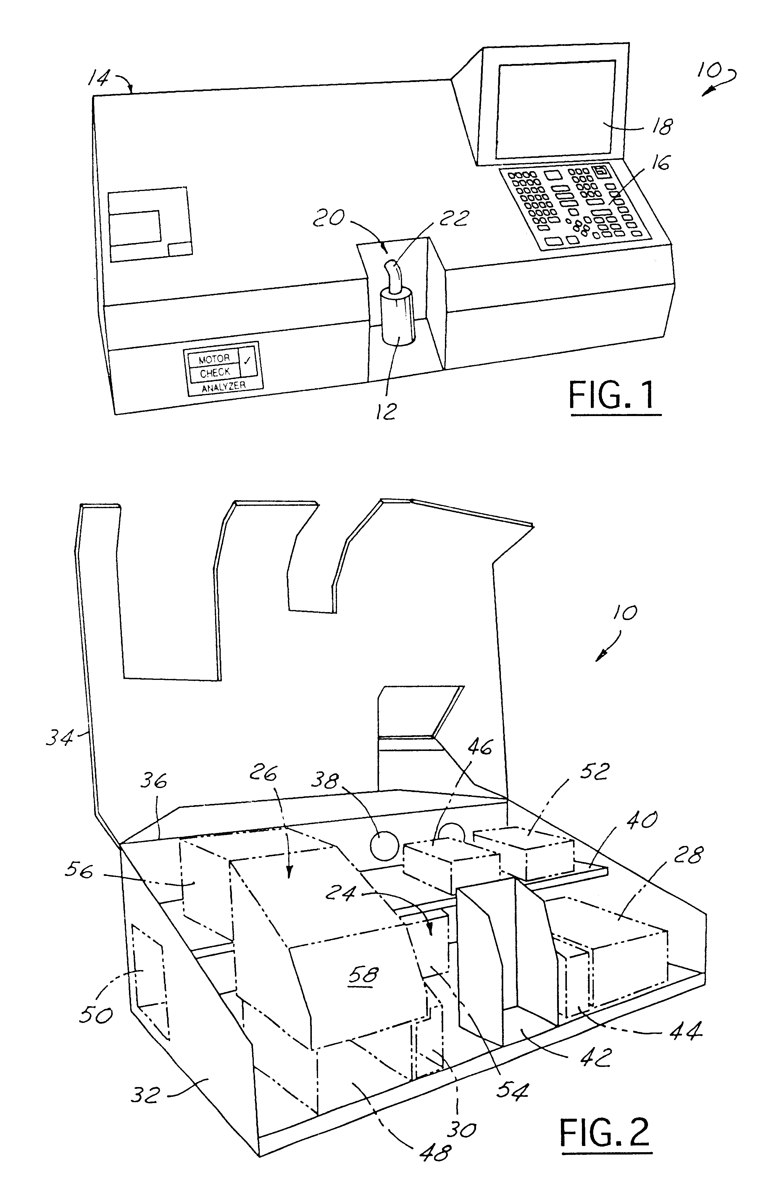
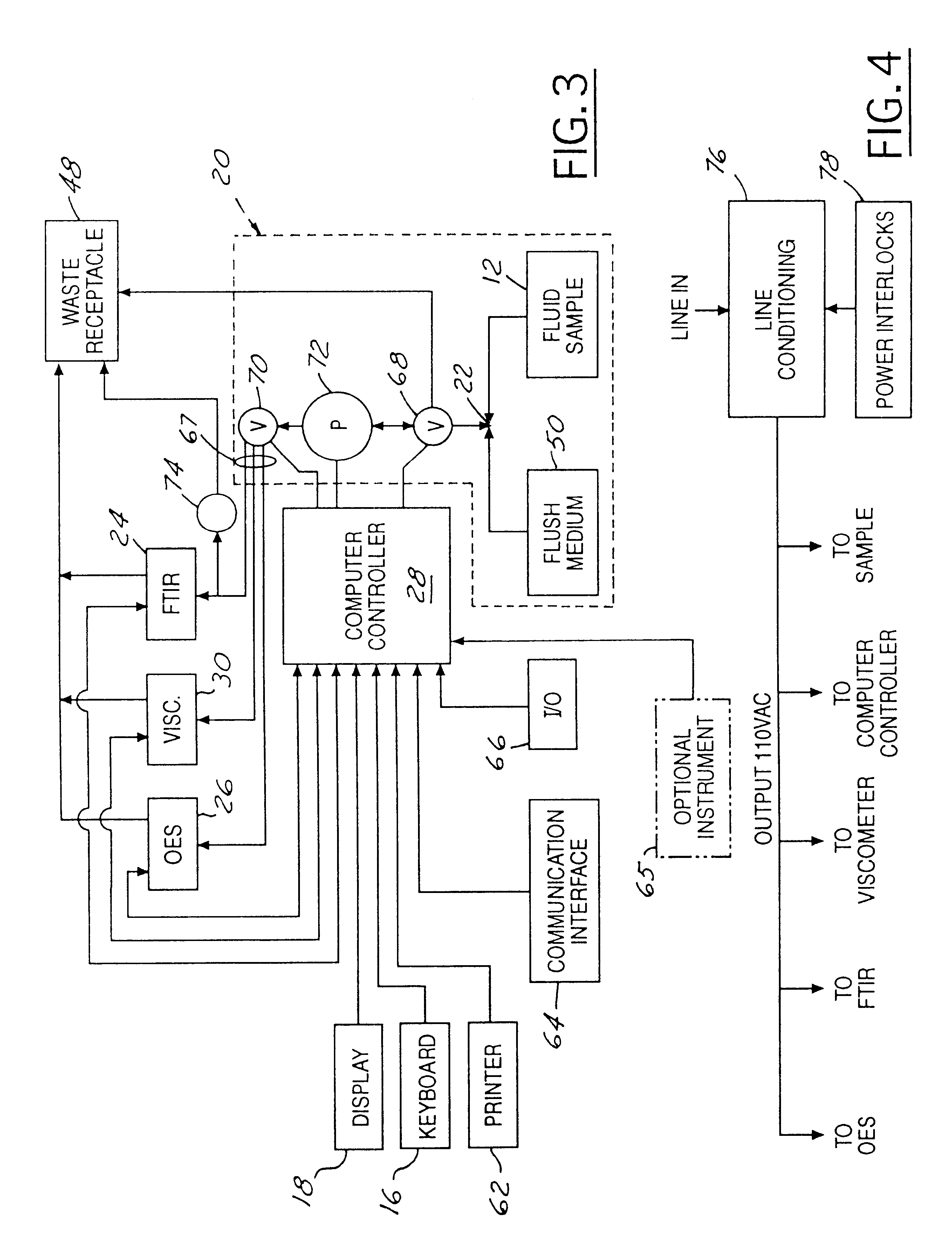
An apparatus (10) for analyzing lubricant oils and functional fluids includes an optical emission spectrometer (OES) (26) having a substantially continuously valued wavelength versus intensity output (140). The OES (26) analyzes light captured from a spark emission stand (58) through which the fluid sample is flowed. An expert system (160-172) operates according to a set of Rules, and generates diagnostic text (174) for an operator based on the information about the fluid sample provided by the OES (26) and other measurement devices. The apparatus (10) includes an airflow passage (154) in the OES (26) spark enclosure that is characterized by airflow substantially parallel to the spark electrodes (128, 130) promoting even-wear of the electrodes.

Description

1. Technical FieldThis invention relates generally to an apparatus and method for analyzing a fluid sample, and, more particularly, to a self-contained analyzer for on-site use and analysis.2. Discussion of the Related ArtThere has been much interest and investigation into apparatus and methods for obtaining accurate analysis of lubricating oils (used and fresh) as well as functional fluids. The term "functional fluids" relates to liquid materials used in mechanical equipment, and which may be or may perform primarily lubrication and / or power transmission functions (e.g., gearbox oils, automatic transmission fluid, machine oils and hydraulic fluids or oils, etc.). "Functional fluids" also includes coolants, thermal transmission media, and fuels. The reasons for such interest include, but are not limited to, (i) the assessment of the constituent, condition and quality of the oil / fluid, (ii) the condition of the equipment from which the oil / fluid was drawn, and (iii) the condition of ...

Claims


Application Information

Patent Timeline
Patent Type & Authority Patents(United States)
IPC IPC(8): G01N21/27G01N21/62G01N21/67G01N21/69G01N33/26G01N33/30G01N21/25G01N33/28G01J3/443G01J3/28
CPCG01J3/443G01N21/274G01N21/67G01N21/3577G01N33/2847G01N33/2858G01N33/2888G01N33/30G01N21/69G01J3/28
Inventor COATES, JOHNROSENBAUM, NEILBRIDGMAN, STEPHEN
Owner SPECTRO SCI INC
Learn More