
Multiple stage decimation filter

a decimation filter and multi-stage technology, applied in the field of decimation filters, can solve the problems of complex and difficult implementation of one-stage finite impulse response filters (fir) or one-stage infinite impulse response filters (iif), and the quantization noise can become quite severe in the higher frequency bands above the base band, and the second stage of the decimation filter is more complicated than the first stag

Inactive Publication Date: 2002-06-18
SONIC INNOVATIONS
View PDF86 Cites 15 Cited by
  • Summary
  • Abstract
  • Description
  • Claims
  • Application Information

AI Technical Summary

Benefits of technology

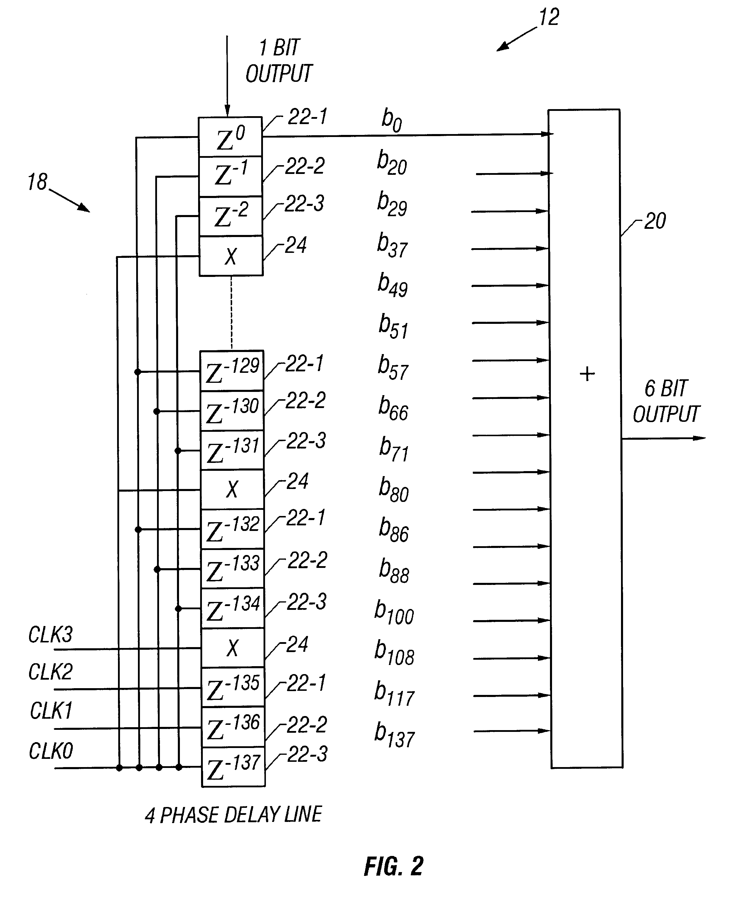
According to another aspect of the present invention, the zero insertion filter includes a serial shift register and an adder. The serial shift register is implemented as a four phase delay line to reduce the number of storage units in the serial shift register that are required for a given number of delay time periods. In the four phase delay line for serial shift register there are storage cells which are divided sequentially into groups of three storage cells. After each group of three storage cells, a free storage cell is disposed. Four non-overlapping clock signals CLK0, CLK1, CLK2, and CLK3 are provided to each of the storage cells and the free storage cells, respectively. By employing a four phase delay line to implement the serial shift register, rather than the more common two-phase delay line that includes a free storage cell between each storage cell, the amount of integrated circuit area required to implement the serial shift register is significantly reduced.

Problems solved by technology

Quantization noise is typically quite minimal in the base band, however, quantization noise can become quite severe in higher frequency bands above the base band.
To meet these criteria in the decimation filter, a one stage finite impulse response filter (FIR) or a one stage infinite impulse response filter (IIF) is quite complicated and difficult to implement.
The second stage of the decimation filter is more complicated to implement than the first stage.

Method used


Image

  • Multiple stage decimation filter
  • Multiple stage decimation filter
  • Multiple stage decimation filter

Examples


Embodiment Construction

Those of ordinary skill in the art will realize that the following description of the present invention is illustrative only and not in any way limiting. Other embodiments of the invention will readily suggest themselves to such skilled persons.

According to the present invention, a decimator suitable for use with an oversampled A / D modulator in an A / D converter is disclosed herein. The decimator is implemented as a filter having high attention in the stop band and a steep transition between the stop band and the pass band of the decimation filter. According to the present invention, the high attenuation in the stop band and a steep transition between the stop band and the pass band of the filter implementing the decimator are desired to prevent the quantization noise and out-of-band noise or signal from aliasing back into the base band after the high sample rate output from the A / D modulator is down sampled by the decimator.

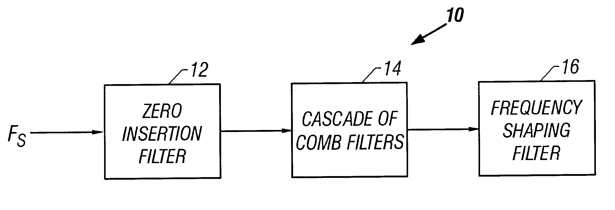
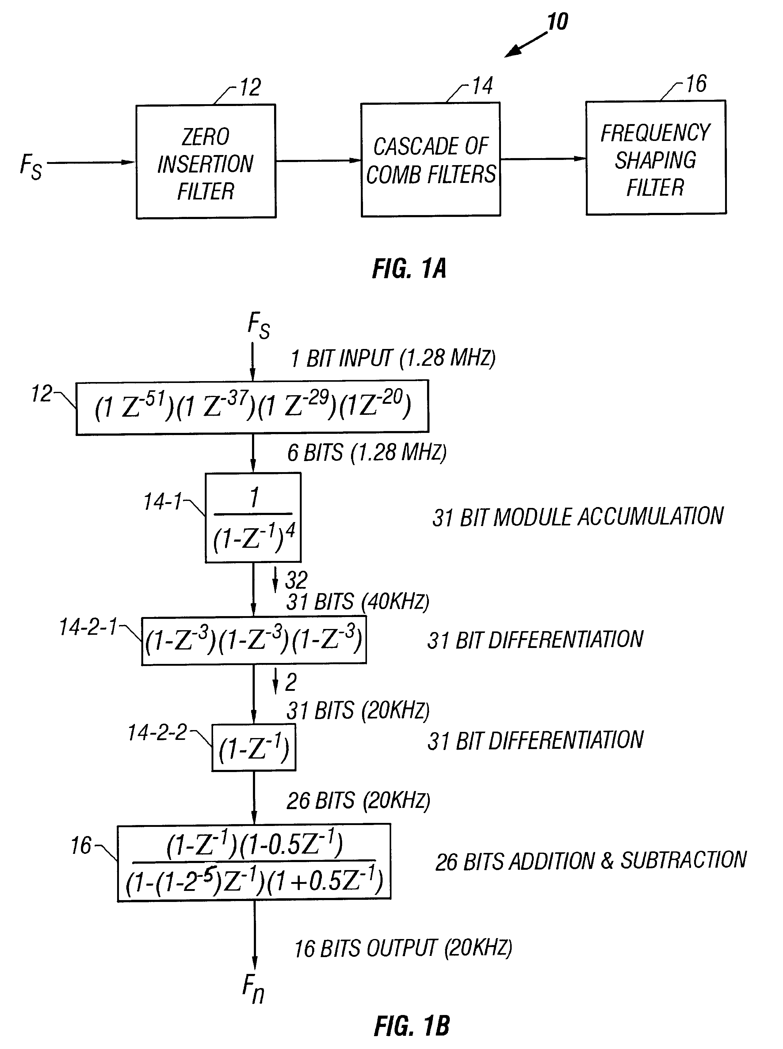
Turning now to FIGS. 1A and 1B, block diagrams of a decimat...


PUM


Abstract

A decimation filter includes a zero insertion filter having an input and an output, wherein the input forms an input of the decimation filter; a cascade of four comb filters having a first accumulator stage and a second stage having a first differentiator portion and second differentiator portion wherein the first stage has an input coupled to the output of the zero insertion filter and an output, the first differentiator portion has an input coupled to the output of the first stage and an output, and the second differentiator portion has an input coupled to the output of the first differentiator portion and an output, and a frequency shaping filter having an input and an output, wherein the input is coupled to the output of the second differentiator portion and the output forms an output of the decimation filter.

Description

1. Field of the InventionThe present invention relates to decimation filters employed for use in an A / D converter that oversamples the analog signal input to the A / D converter. More particularly, the present invention relates to a multiple stage decimation filter that employs cascaded comb filters and a zero insertion filter to provide high attenuation in the stop band to effectively suppress quantization noise and attenuate out-of-band noise, and a steep transition between the pass band and the stop band.2. The Prior ArtIt is common in audio design and in various types of signal processing to employ an A / D modulator in an A / D converter that samples a signal well above the Nyquist rate to obtain a high resolution A / D converter, since it is well known that the resolution of a Nyquist rate A / D converter is limited by the injection of noise from the digital portion of the A / D modulator that is aliased into the passband. Further, a Nyquist rate A / D converter requires effective anti-alia...

Claims


Application Information

Patent Timeline
Patent Type & Authority Patents(United States)
IPC IPC(8): H03H17/06H03M1/08H03H17/00H03H17/02
CPCH03H17/0671H03H17/0664
Inventor FANG, XIAOLINGHUANG, RENYUAN
Owner SONIC INNOVATIONS
Learn More