
Heat insulator for disc brake

Inactive Publication Date: 2002-06-11
SHIMANO INC
View PDF13 Cites 24 Cited by
  • Summary
  • Abstract
  • Description
  • Claims
  • Application Information

AI Technical Summary

Benefits of technology

Another object of the present invention is to provide a heat insulator that is versatile and can be used with existing disc brake assemblies to dissipate heat transferred to the actuating fluid.
Still another object of the present invention is to provide a heat insulator that is relatively simple and inexpensive to manufacture.

Problems solved by technology

However, one problem with hydraulically actuated disc brakes is that the hydraulic or actuating fluid can become overheated such that vapor-lock occurs.
When vapor-lock occurs, the bicycle wheels can lock up and throw the rider off of the bicycle.
These prior art methods of avoiding vapor-lock have many problems.
One particular problem is that some of these solutions often are expensive to manufacture.
Also, some of these prior art solutions are not completely effective.

Method used


Image

  • Heat insulator for disc brake
  • Heat insulator for disc brake
  • Heat insulator for disc brake

Examples


Embodiment Construction

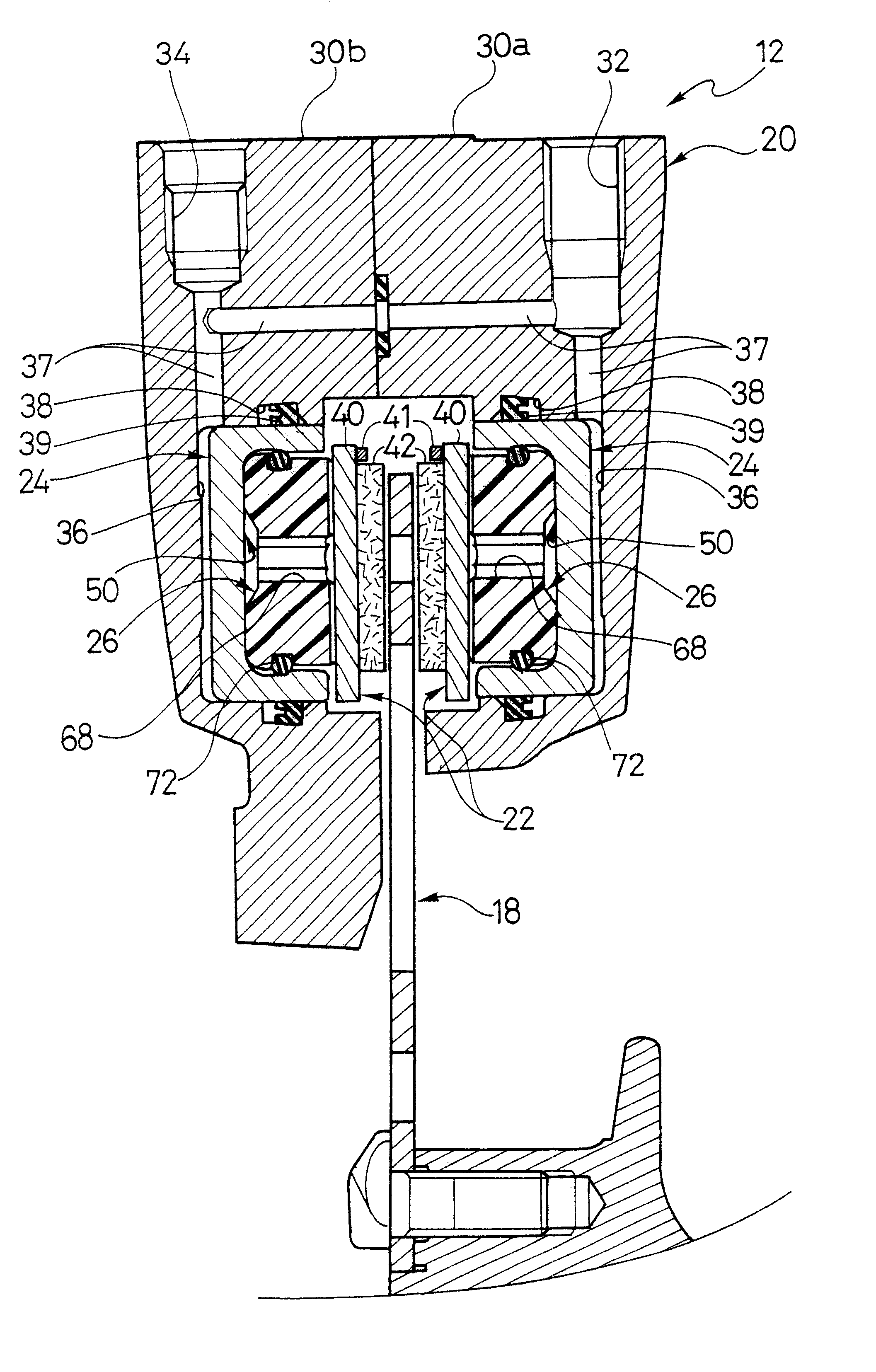
Referring now to FIGS. 16-20, a modified disc brake assembly 112 with a plurality of heat insulators 126 is illustrated in accordance with a second embodiment of the present invention. This second embodiment of the present invention is identical to the first embodiment, except that heat insulators 26 of the first embodiment have been modified in this second embodiment. Specifically, heat insulators 26 have been replaced with modified heat insulators 126 in this second embodiment of the present invention. The other parts of disc brake assembly 112 are identical to the parts of the first embodiment (i.e., disc brake assembly 12). Accordingly, these parts will not be discussed or illustrated in detail herein. Moreover, identical parts will be identified with the same reference numerals in this second embodiment as in the first embodiment.

Each heat insulator 126 is preferably a rigid annular member formed of plastic material with a low heat transfer coefficient. Specifically, each heat ...


PUM


Abstract

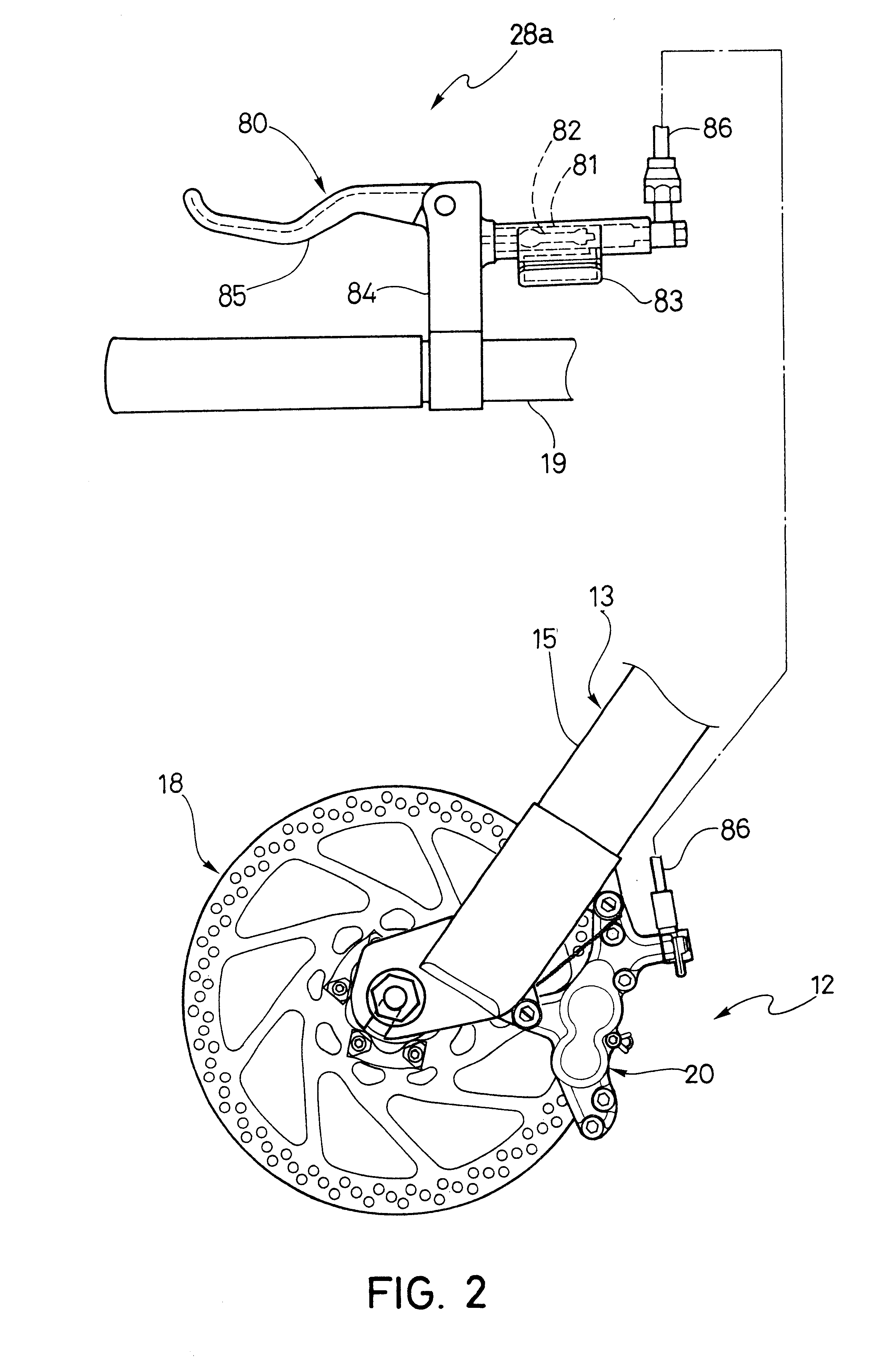
A disc brake assembly is provided with heat insulators to reduce the heat transferred to the hydraulic fluid of the disc brake assembly during braking. The disc brake assembly includes a caliper housing, a first and a second friction member coupled to the caliper housing and one or more pistons movably coupled to the caliper housing to move one or both of the friction members. The first and second friction members form a rotor receiving slot. At least the first friction member is movably coupled to the caliper housing and the piston is movably coupled to the caliper housing to move the first friction member between a release position and a braking position. Each piston has an internal recess to partially receive the heat insulator. The heat insulator is disposed between the piston and the first friction member to prevent heat transfer from the first friction member to the piston. The heat insulator has a first end with a first end surface received in the recess of the piston, a second end with a second end surface spaced from the first end surface and a side wall extending between the first and second end surfaces. The second end is partially received in the recess of the piston and the side wall has a protrusion extending from the side wall to space the heat insulator from the piston. Alternatively, a heat insulator is provided that has a first end with a first end surface received in the recess of the piston, a second end with a second end surface spaced from the first end surface and a side wall extending between the first and second end surfaces. The second end is partially received in the recess of the piston and has a groove formed in the second end surface.

Description

1. Field of the InventionThis invention generally relates to a heat insulator for a disc brake assembly. More specifically, the present invention relates to a heat insulator disposed between a piston and a friction member that reduces the heat transferred from the friction member to the hydraulic fluid of the disc brake assembly.2. Background InformationBicycling is becoming an increasingly popular form of recreation as well as a means of transportation. Moreover, bicycling has become a very popular competitive sport. Whether the bicycle is used for recreation, transportation or competition, the bicycle industry is constantly improving their components. One particular component of the bicycle, which has been extensively redesigned over the past years, is the braking systems of bicycles. In particular, the braking power of the braking systems is constantly being increased.There are several types of bicycle brake devices, which are currently available on the market. Examples of some t...

Claims


Application Information

Patent Timeline
IPC IPC(8): B62L1/00F16D65/14F16D55/228F16D55/22F16D55/224F16D65/18
CPCB62L1/00F16D55/228F16D2125/06F16D2065/785
Inventor UEDA, TOSHIYUKIOHISHI, RIKIMASA
Owner SHIMANO INC
Learn More