
DC current brushless motor driving apparatus and air conditioner with using thereof

Inactive Publication Date: 2002-05-28
HITACHI LTD
View PDF4 Cites 61 Cited by
  • Summary
  • Abstract
  • Description
  • Claims
  • Application Information

AI Technical Summary

Benefits of technology

An object according to the present invention is, for dissolving such the problems mentioned in the above, to provide a DC brushless motor driving apparatus and an air conditioner driven thereby, being able to drive the DC brushless motor under stable condition with good efficiency, even in a case of driving the DC brushless motor in a wide range of the revolution number, or in a case of driving it under a wide range of the load condition.
Another object according to the present invention is, for dissolving such the problems mentioned in the above, to provide a DC brushless motor driving apparatus and an air conditioner driven thereby, being able to detect the commutation timings of a group of semiconductor switching elements of an inverter with certainty, when starting the DC brushless motor or operating it under a light load condition, thereby enabling a stable operation control thereof.
The present invention relates to a DC current brushless motor driver apparatus using an inverter therein, and in particular, it relates to a DC current brushless motor driver apparatus and an air driven thereby, wherein a relative position (hereinafter, being called by "magnetic pole position") between armature windings (stator windings) and stator windings is detected by a velocity or speed electromotive force which is induced across the stator windings, so as to control a revolution number thereof.

Problems solved by technology

For the purpose of driving the DC brushless motor under a stable condition with good efficiency, there is a necessity that the frequency characteristic must be set, so that the phase difference of around 90.degree. is maintained within the predetermined range of the basic frequency of the induction voltages, however for example, in a case where the range of the basic frequency of the induction voltages is desirous to be extended or expanded (i.e., a variable range of revolution number of the DC brushless motor is desirous to be extended or expanded), there is a problem that it is impossible to maintain the phase difference between the induction voltage and the triangle-like signal at around 90.degree., depending upon the frequency characteristic of the filters.
However, it is enough to make the time constant of the filter large for the purpose of smoothing the wave-form of the triangle-like signal, but it causes time delay in the signal, therefore there is an upper limit in setting of the time constant of the filters.
By the way, in the DC brushless motor, the wave-form of the spike voltage is changed depending upon a load of the motor, but there is the upper limit in setting the time constant of the filters, then there is a problem that it is impossible to maintain the phase difference between the induction voltage and the triangle-like signal at 90.degree., since the phase of the triangle-like signal is fluctuated in an appearance thereof due to change in the wave-form of the triangle-like signal.

Method used


Image

  • DC current brushless motor driving apparatus and air conditioner with using thereof
  • DC current brushless motor driving apparatus and air conditioner with using thereof
  • DC current brushless motor driving apparatus and air conditioner with using thereof

Examples


first embodiment

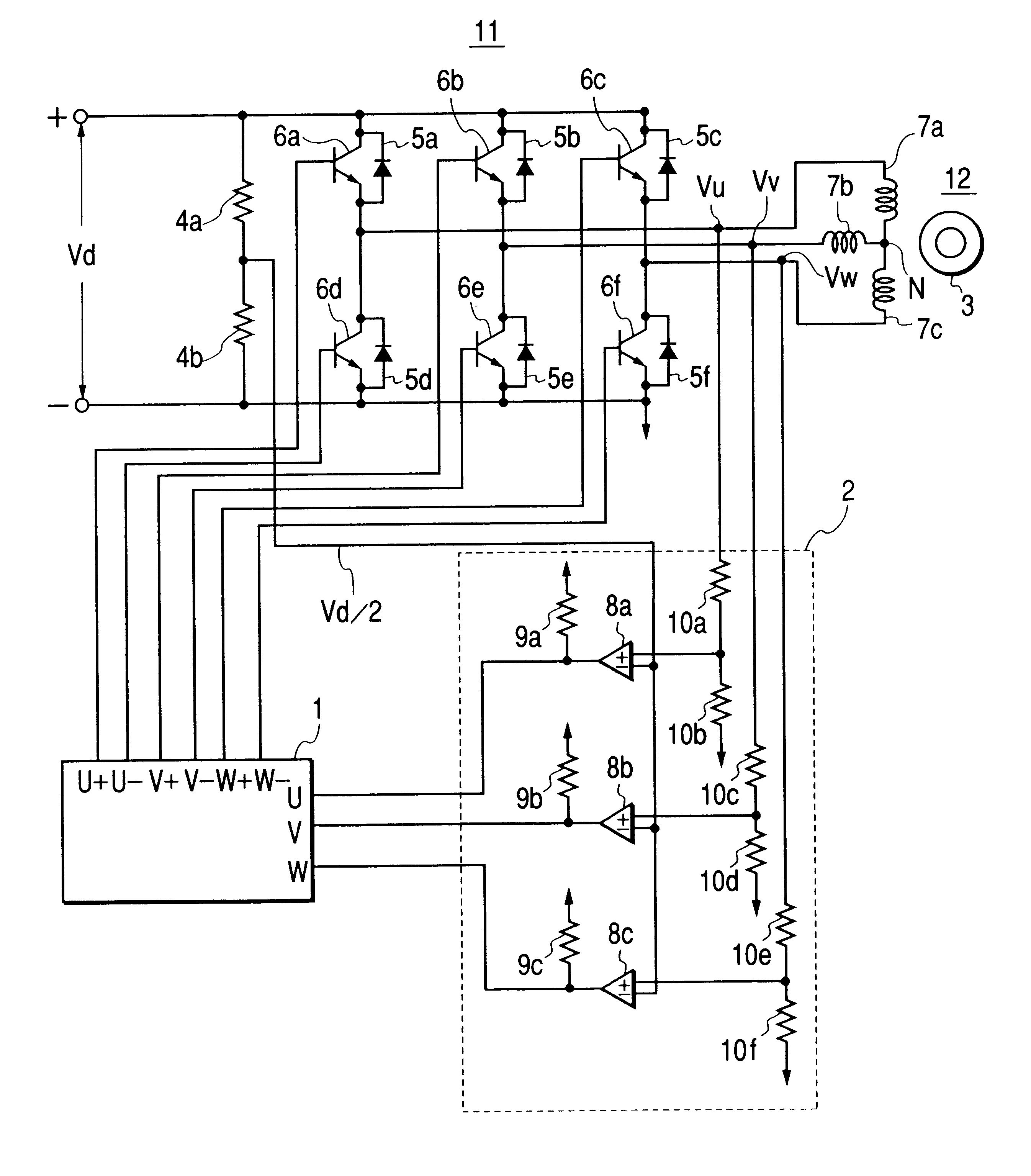
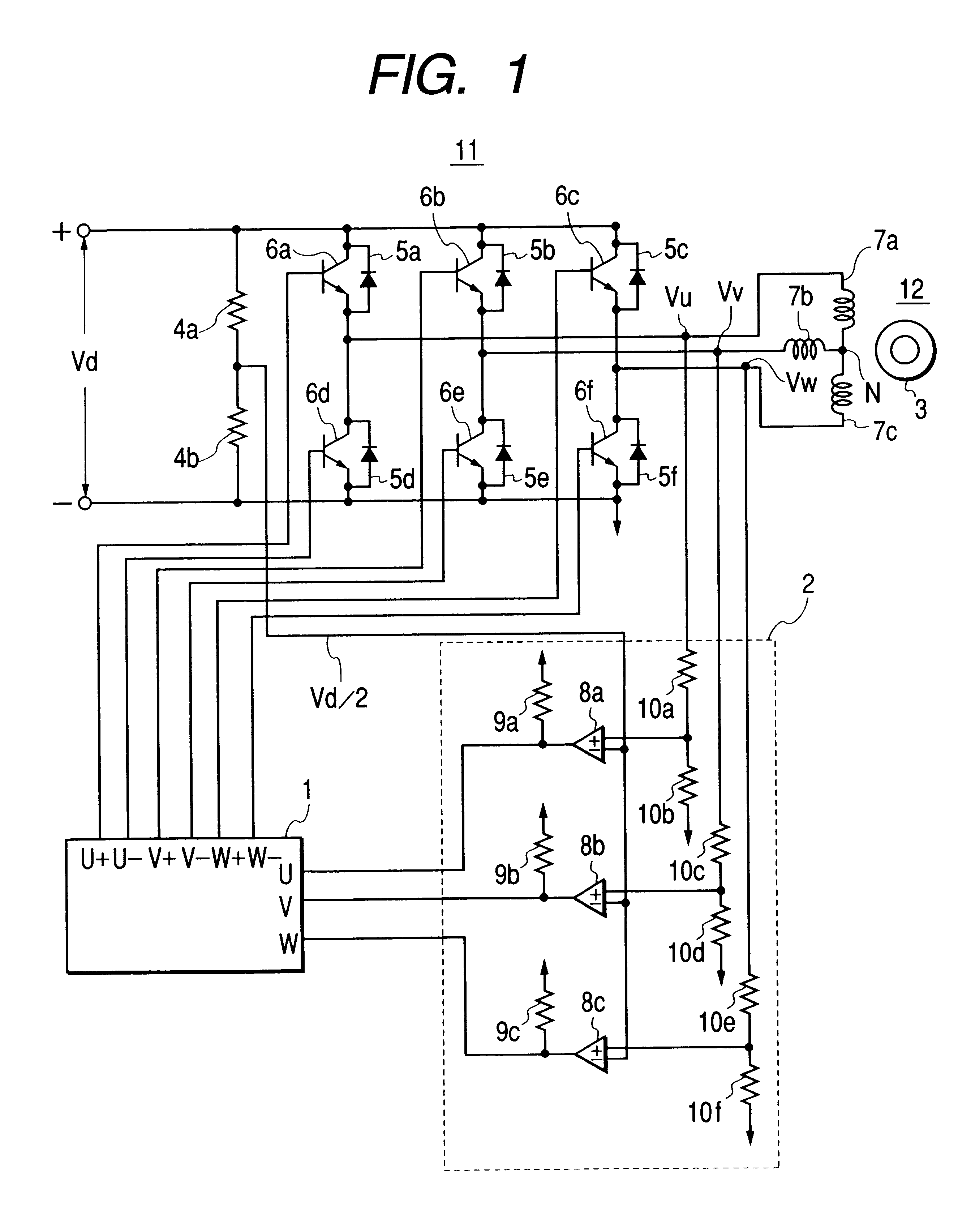
FIG. 1 shows a circuit diagram of a direct current (DC) brushless motor driver apparatus according to the present invention, wherein a reference numeral 1 indicates a micro-computer, 2a position detector circuit of rotor magnetic poles, 3a rotor, 4a and 4b detection resistors of a reference voltage, 5a-5f flywheel or return-current diodes, 6a-6f semiconductor switching elements, 7a-7c stator windings, 8a-8c comparators, 9a-9c pull-up resistors; 10a-10f detecting resistors of a motor terminal voltage, 11 an inverter, and 12 a DC brushless motor.

In the same figure, the inverter 11 is constructed with the semiconductor switching elements 6a-6f being in a bridge-connection and the flywheel diodes 5a-5f which are connected in parallel therewith, and to this inverter 11 is applied a DC power source voltage Vd. Also, the rotor 3 and the stator windings 7a-7c construct the DC brushless motor 12, and to each of the stator windings 7a-7c in the respective phases of the DC brushless motor 12 i...

second embodiment

Next, explanation will be given on a second embodiment according to the present invention.

FIG. 6 is a circuit diagram for showing a second embodiment of the DC bruchless motor driving apparatus and the air conditioner with using thereof, according to the present invention, wherein a reference numeral 13 indicates a DC voltage detector, and the elements corresponding to those shown in the FIG. 1 are attached with the same reference numerals, so as to omitted duplication of the explanation thereof.

In the air conditioner, it is general to use different commercial AC power sources, such as 100 V and 200 V, as the commercial AC power source therefor. Then, in this second embodiment, as shown in the FIG. 6, it is so constructed that the DC voltage detector 13 is added to the construction shown in the FIG. 1, wherein the DC power source voltage Vd of the inverter 11 is detected by this DC voltage detector 13, thereby to determine a kind of the commercial AC power source (for example, the c...


PUM


Abstract

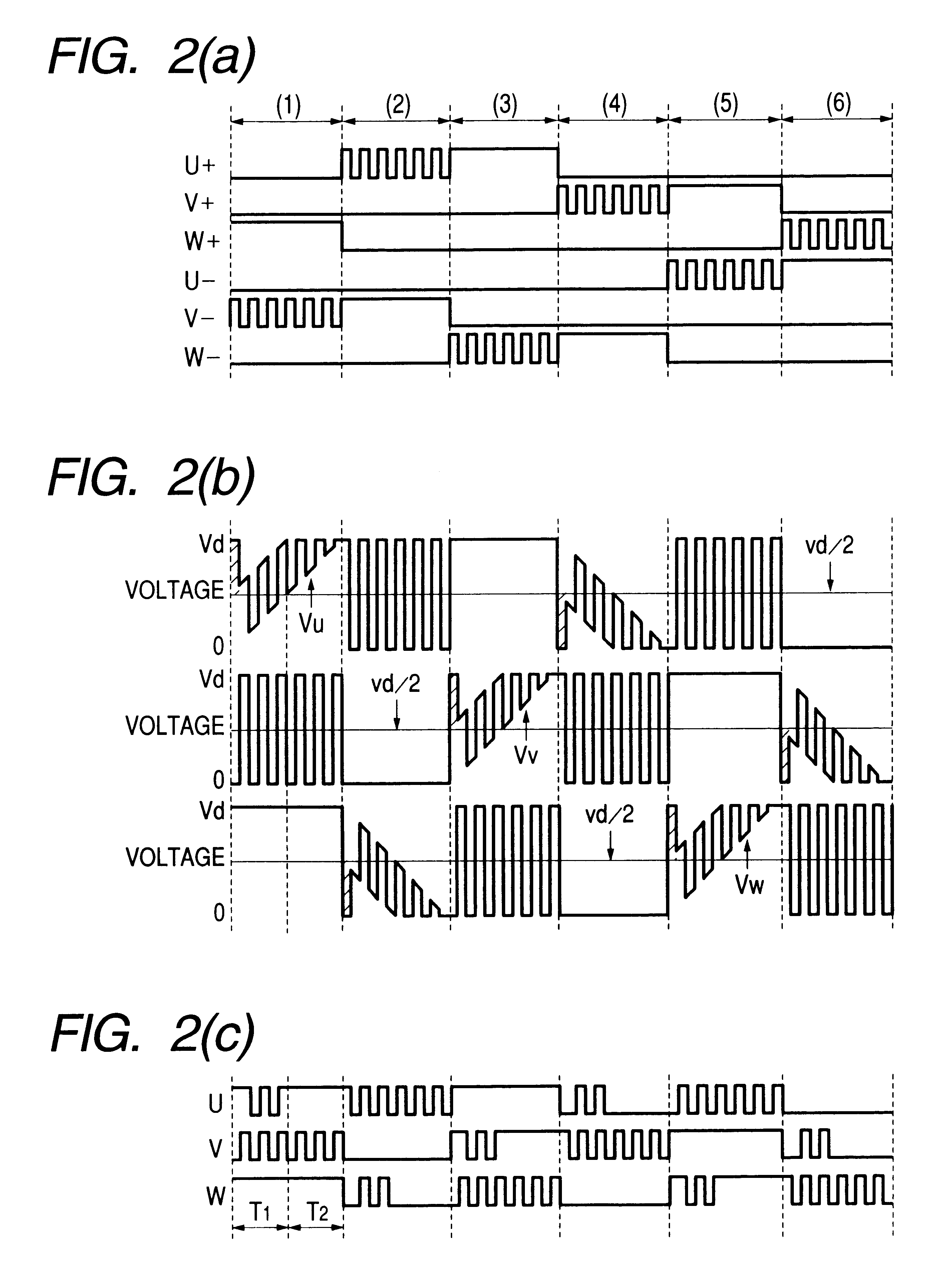
For detecting commutation timing of an inverter when operating a DC brushless motor under a starting thereof or a light load condition, with certainty, a micro-computer generates driving signals so as to drive switching elements of the inverter by PWM signals of those driving signals, in a predetermined order by every turn-on interval, thereby supplying driving current to the DC brushless motor, wherein a timing for exchange between the turn-on intervals (i.e., the commutation timing) is detected by detection of level of magnetic pole position detecting signals upon a basis of the PWM signals. Here, the minimum ON time of the PWM signals is set at a time being detectable in the level of the magnetic pole position detecting signals, however the frequency of the PWM signals is lowered when the DC brushless motor is operated in starting or under a light load condition, so as to make duty ratio of the PWM signals fit to the operation in the starting or under the light load condition, thereby enabling to ensure the minimum ON time of the PWM signals.

Description

1. Field of the InventionThe present invention relates to a DC current brushless motor driver apparatus using an inverter therein, and in particular, it relates to a DC current brushless motor driver apparatus and an air driven thereby, wherein a relative position (hereinafter, being called by "magnetic pole position") between armature windings (stator windings) and stator windings is detected by a velocity or speed electromotive force which is induced across the stator windings, so as to control a revolution number thereof.2. Description of Prior ArtAs a conventional example of a DC brushless motor driving apparatus is described, for example in Japanese Patent Publication No. Sho 59-36519 (1984), wherein control of a revolution number thereof is conducted by detecting magnetic pole positions of a rotor, i.e., the relative positions between the magnetic rotor (herein after, being called only by a "rotor") and stator windings due to the velocity electromotive force (induction voltage...

Claims


Application Information

Patent Timeline
IPC IPC(8): H02P6/08H02P6/00H02P6/18H02P6/14H02P6/20H02P6/06H02P6/182
CPCH02P6/085H02P6/20H02P6/185
Inventor WAKUI, TOYOMITSUKATOU, KOUJIOKUYAMA, ATSUSHITERAUCHI, HIDEKIMAKITA, MINORUKANEKO, KISASUIWASAKI, MASAYUKITAMURA, KENJI
Owner HITACHI LTD
Learn More