
Thermoplastic resin composition, molding material, and molded article thereof

a technology of thermoplastic resin and composition, which is applied in the direction of transportation and packaging, vehicle components, special tyres, etc., can solve the problems of affecting the appearance of molded articles, reducing the impact strength and moldability, and increasing the specific gravities of thermoplastics

Inactive Publication Date: 2002-05-07
TORAY IND INC
View PDF16 Cites 115 Cited by
  • Summary
  • Abstract
  • Description
  • Claims
  • Application Information

AI Technical Summary

Benefits of technology

In order to satisfy the electrical conductivity requirement and the appearance requirement of the molded article, it is preferable to control the amount of the component [A] added in the thermoplastic resin composition at a low level. However, in such a case, the electrical conductivity decreases. However, the component [B] achieves a high electrical conductivity and the reduction in the thin-wall moldability is minimized. Therefore, the advantage of the invention is apparent.

Problems solved by technology

An attempt to raise the electrical conductivity by increasing the amount of the electrically conductive fiber (or electrically conductive filler) almost always results in unreasonable increases in the costs and the specific gravities of the thermoplastic resin composition and molded articles thereof, and gives rise to problems of, for example, considerable reductions in the impact strength and the moldability (flowability during a molding process or the like) and, moreover, impairment of the appearance of molded articles.
However, none of these proposals satisfies the requirements of high electrical conductivity and thin-wall moldability altogether.

Method used


Image

  • Thermoplastic resin composition, molding material, and molded article thereof
  • Thermoplastic resin composition, molding material, and molded article thereof
  • Thermoplastic resin composition, molding material, and molded article thereof

Examples


examples 1 , 2

Examples 1, 2, Comparative Examples 1, 2

Desired amounts of components [B] and [D], other components and a component [C] were sufficiently melted and kneaded and extruded by a double-screw extruder (the barrel temperature being 250.degree. C.) to prepare master pellets in which the components [B] and [D] were homogenized in the component [C].

Next, the master pellets dry-blended at a desired proportion were put in via a main hopper of a double-screw extruder (the barrel temperature being 250.degree. C.). While the well-kneaded melt was being extruded, the component [A] processed into chopped strands by using a sizing agent was put in via a side hopper so as to impregnate the component [A] chopped strands with various components including at least the component [C]. The resultant extruded resin-gut containing discontinuous component [A] was cooled, and then was cut into 5 mm by a cutter, thereby obtaining ordinary pellets.

The kinds and compounding proportions of the components are show...

examples 3-10

, Comparative Examples 3-7

Desired amounts of components [B] and [D], other components and a component [C] were extruded by a double-screw extruder (the barrel temperature being 250.degree. C.) to prepare master pellets in which the components [B] and [D] were homogenized in the component [C].

Next, while the master pellets dry-blended at a desired proportion were extruded in a well melted and kneaded state by a single-screw extruder (the barrel temperature being 250.degree. C.) into a crosshead die attached to a distal end of the extruder, the contimuous component [A] tow was sequentially supplied into the crosshead die to sufficiently impregnate the component [A] tow with various components including at least the component [C]. The crosshead die is a device for impregnating the component [A] tow with molten resin and the like while opening the fibers of the component [A] tow in the die. The resultant strand containing continuous component [A] tow was cooled, and then was cut into 7 ...

examples 11-14

First, desired amounts of components [C] were extruded by a double-screw extruder (the barrel temperature being 250.degree. C. in Examples 11 and 12, and 280.degree. C. in Example 13) to prepare blended resin pellets in which the plural components [C] were homogenized.

Next, components [B] and [D], other components and the blended resin pellets or the component [C] were extruded by a double-screw extruder (the barrel temperature being 250.degree. C. in Examples 11, 12 and 14, and 280.degree. C. in Example 13) to prepare master pellets in which the components [B] and [D] were homogenized in the component [C].

After that, while the master pellets dry-blended at a desired proportion were extruded in a well melted and kneaded state by a single-screw extruder (the barrel temperature being 250.degree. C. in Examples 11, 12 and 14, and 290.degree. C. in Example 13) into the crosshead die attached to a distal end of the extruder, the contimuous component [A] tow was sequentially supplied into...


PUM

PropertyMeasurementUnit
thicknessaaaaaaaaaa
volume resistivityaaaaaaaaaa
wt. %aaaaaaaaaa

Abstract

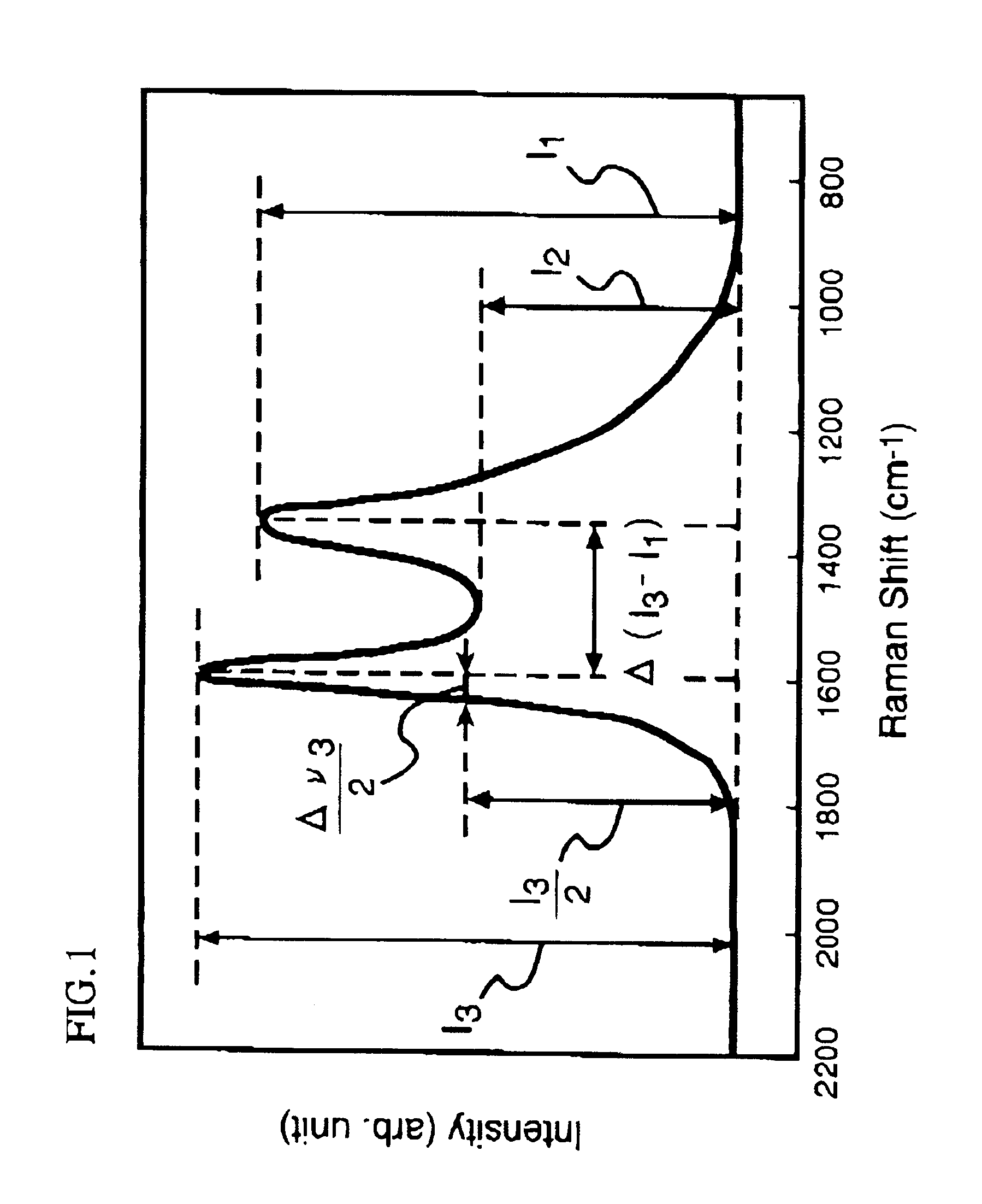
A thermoplastic resin composition capable of providing a thin walled molded article whose flame retardancy with a thickness of 1.6 mm ({fraction (1 / 16)} inch) in accordance with an UL 94 standard is V-0 or better, and which comprises the following components [A], [B] and [C], wherein the component [B] satisfies the following conditions (B1) and / or (B2):[A]: an electrically conductive fiber;[B]: a carbon powder;[C]: a thermoplastic resin;(B1): Raman scattering intensity ratio I2 / I1 is 0.55-0.8;(B2): Raman scattering intensity ratio I2 / I3 is 0.54-0.8; whereI1: local maximum value of Raman scattering intensity appearing near a Raman shift of 1360 cm-1;I2: local minimum value of the Raman scattering intensity appearing near a Raman shift of 1480 cm-1;I3: local maximum value of the Raman scattering intensity appearing neat a Raman shift of 1600 cm-1.

Description

The present invention relates to a thermoplastic resin composition having high electrical conductivity, excellent thin-wall moldability, good appearance and high flame retardancy, and to a molding material and a molded article that are made from the thermoplastic resin composition.BACKGROUND ARTSIt has conventionally been known that a thermoplastic resin composition having a desired electrical conductivity and a molded article thereof are obtained by compounding an electrically conductive fiber (or an electrically conductive filler) with a resin.Thermoplastic resin compositions obtained by compounding electrically conductive fibers (or electrically conductive fillers) and molded articles thereof as mentioned above typically exhibit volume resistivity above 2.5 .OMEGA..multidot.cm, and are rarely applied to uses where a volume resistivity less than that value is preferable, for example, electromagnetic wave shield materials and the like. In cases where a volume resistivity of less th...

Claims


Application Information

Patent Timeline
Patent Type & Authority Patents(United States)
IPC IPC(8): C08K3/00C08K3/04C08K7/00C08K7/02
CPCC08K7/02C08K3/04
Inventor WADAHARA, EISUKEYOSHIOKA, KENICHIISHIBASHI, SOICHI
Owner TORAY IND INC
Learn More