LCD device having a back light

Inactive Publication Date: 2002-04-30
GOLD CHARM LTD
View PDF6 Cites 19 Cited by
  • Summary
  • Abstract
  • Description
  • Claims
  • Application Information

AI Technical Summary

Benefits of technology

In accordance with the LCD device of the present invention, the reflecting plate reflects the back light uniformly toward the LCD panel and, in addition, has a function for shielding the LCD panel against the noise generated by the printed circuit board. The reflecting panel having the conductive film only slightly raises the total costs for the LCD device, differently from the conventional LCD device having a large printed circuit board.

Problems solved by technology

First, the size of the printed circuit board 34 is extremely large due to having a reflecting function for the back light of the LCD panel. The large size of the printed circuit board increases the total costs for the LCD device. More specifically, the cost for the printed circuit board generally depends on the number of printed circuit boards that can be obtained from a single board stuff having a fixed size.
Second, the LCD panel has irregularities in brightness of the screen. More specifically, the printed circuit board 34 generally mounts thereon a plurality of electric components such as a drive LSI for driving the LCD panel and a bypass capacitor used for a power source line for the LCD device. These electric components are generally attached onto one of the surfaces of the printed circuit board by using solder. This often generates a warped or wavy surface on the printed circuit board due to the heat generated in the soldering process. The warped or wavy surface hinders the reflecting surface of the printed circuit board from reflecting uniform light, whereby the LCD panel has the irregularities in brightness. In addition, it is usual that the electric components are mounted on the printed circuit board at the depressions of the printed circuit board which are formed for this purpose. The depressions, which hardly reflects light, also cause the irregularity or reduction in the brightness of the screen.
The reflecting panel having the conductive film only slightly raises the total costs for the LCD device, differently from the conventional LCD device having a large printed circuit board.

Method used


Image

  • LCD device having a back light
  • LCD device having a back light
  • LCD device having a back light

Examples


first embodiment

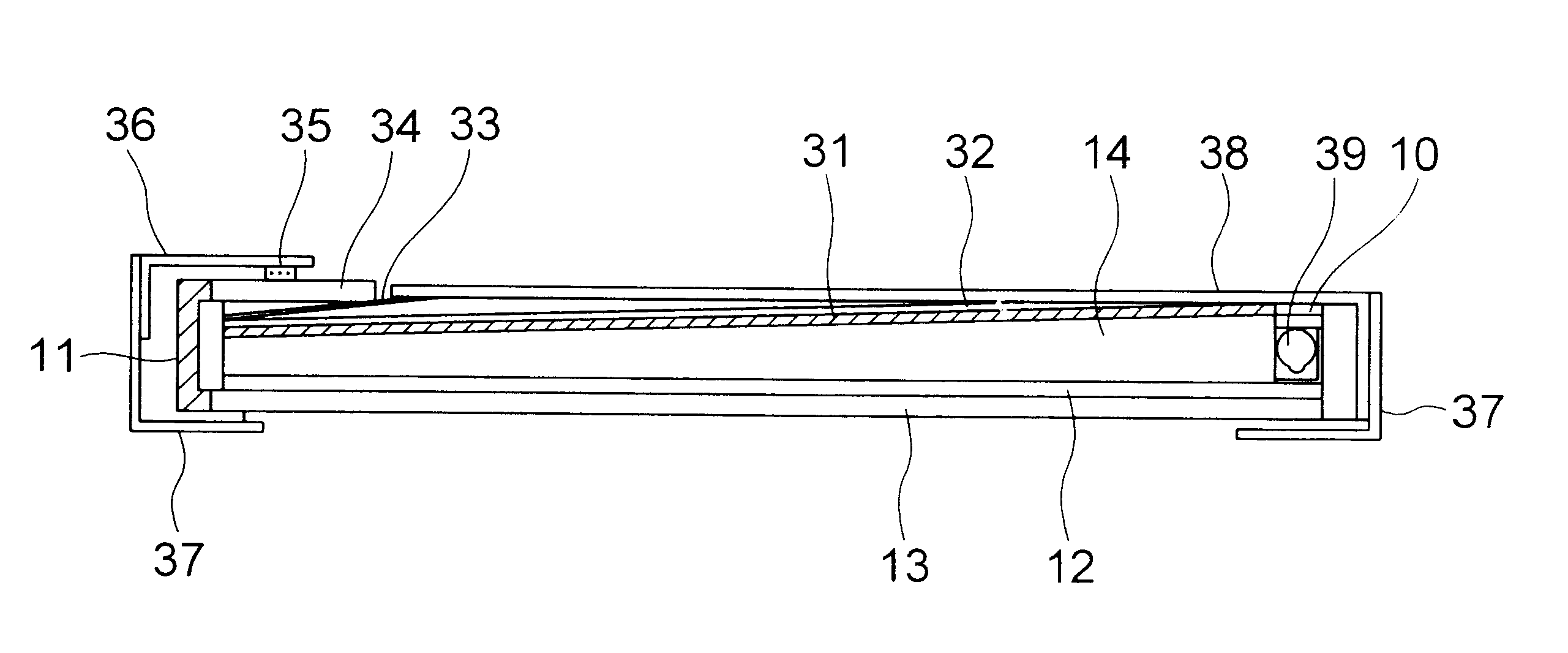
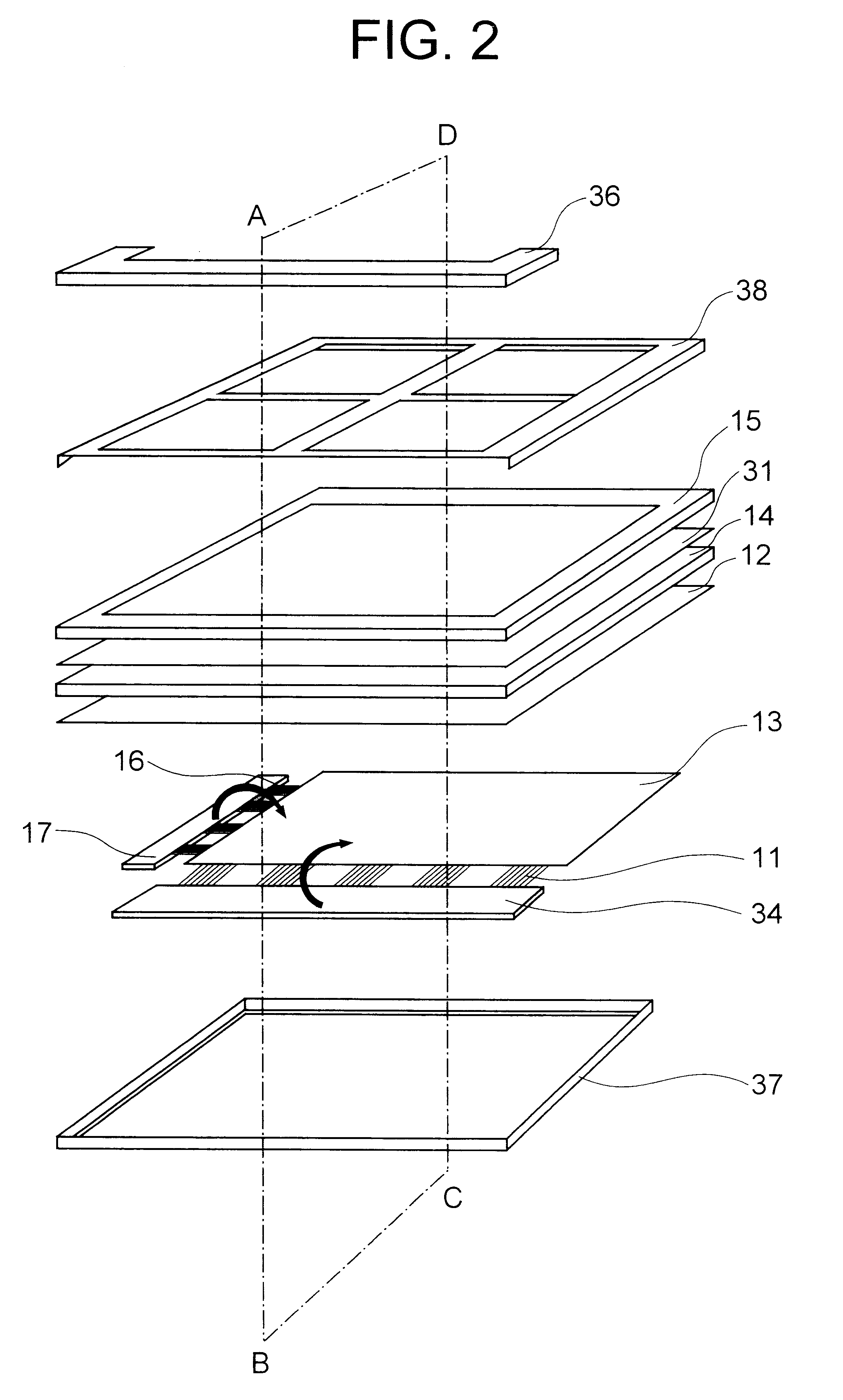
Referring to FIG. 2, a LCD device according to the present invention includes a LCD panel 13, a light-conductive sheet 14 disposed at the rear side of the LCD panel 13 for conducting back light emitted from a light source (or lamp) not shown, a prism sheet 12 sandwiched between the LCD panel 13 and the light-conductive sheet 14 for guiding the back light conducted by the light-conductive sheet 14 toward the entire area of the LCD panel 13, and a reflecting plate 31 disposed at the rear side of the light-conductive sheet 14 for reflecting the back light which has passed the rear surface of the light-conductive sheet 14. The reflecting plate 31 is covered at the rear side thereof by a conductive film, which is connected to the ground.

The prism sheet 12, light-conductive sheet 14 and reflecting plate 31 are held by a back light chassis 15 at the rear side of the LCD panel 13. A rear shield 38 reinforces the back light chassis 15 to assist the same to hold the prism sheet 12, light-cond...

second embodiment

Referring to FIG. 4, a LCD device according to the present invention has a contact member 35 made of stainless steel having a spring function. The contact member 35 electrically connects a ground pattern of the printed circuit board 34 and the conductive film 32 formed on the rear surface of the reflecting plate 31. The conductive film 32 is formed by vacuum evaporation of a metal such as aluminum. In an alternative, the conductive film 32 may be formed by metallic plating, or may be a conductive sheet adhered onto the rear surface of the reflecting plate 31.

The conductive film 32 disposed adjacent to the printed circuit board 34 functions as a ground layer for the printed circuit board 34. Thus, a ground layer can be omitted on the front side of the printed circuit board 34.


PUM


Abstract

A LCD device has a LCD panel and a drive TCP for driving the LCD panel. Back light is guided to the rear surface of the LCD panel by a light-conductive sheet. The leakage back light passed the rear surface of the light-conductive sheet is reflected by a reflecting plate having a conductive film at the rear surface of the reflecting plate. The conductive film is connected to a ground pattern of the printed circuit board which transfers signals to the drive TCP. The reflecting plate has both functions for reflecting back light and shielding the LCD panel against the noise generated by the printed circuit board.

Description

(a) Field of the InventionThe present invention relates to a LCD (liquid crystal display) device having a back light and, more particularly, to the structure of a reflecting plate for reflecting the back light from the rear side of the LCD panel toward the front side thereof.(b) Description of the Related ArtA LCD device having a back light generally includes a reflecting plate at the rear side of the LCD panel, with a light-conductive sheet sandwiched between the LCD panel and the reflecting plate. The reflecting plate reflects the leakage light, which has passed through the rear surface of the light-conductive sheet, toward the front side of the LCD panel, thereby saving the light power resource. In general, the LCD panel, the light-conductive sheet and the reflecting plate have an equivalent size.Patent Publication JP-A-4-371924 describes a structure shown in FIG. 1, wherein a printed circuit board 34 including a plurality of interconnect layers is disposed at the rear side of th...

Claims


Application Information

Patent Timeline
IPC IPC(8): G02F1/13G02F1/1335G09F9/00G02F1/13357G02F1/1345
CPCG02F1/133615G02F2203/02G02F2001/133334G02F1/133334G02F1/1335
Inventor ARAI, NOBUHIRO
Owner GOLD CHARM LTD
Why Eureka
Try Eureka