
Motion detector based on the doppler principle

a technology of motion detector and doppler principle, applied in the direction of burglar alarm short radiation actuation, instruments, measurement devices, etc., can solve the problems of reducing the noise of the detector, making the distinction between distant humans and small domestic animals at a lesser distance considerably more difficult or even impossible, and achieving the effect of superior noise suppression and other interference suppression

Inactive Publication Date: 2002-04-30
VANDERBILT INT GMBH +1
View PDF14 Cites 137 Cited by
  • Summary
  • Abstract
  • Description
  • Claims
  • Application Information

AI Technical Summary

Benefits of technology

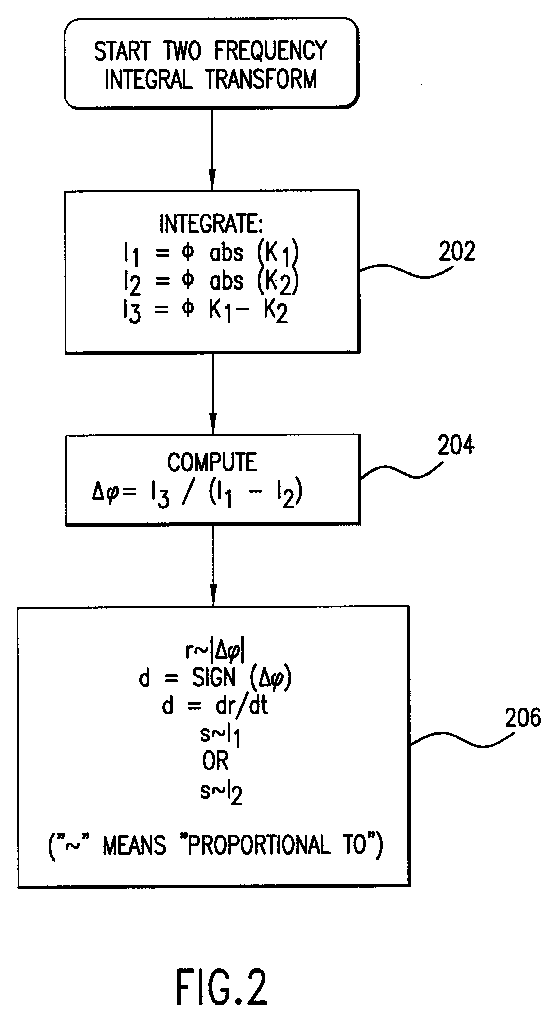
The above objects are achieved, according to the invention, in that the phase difference is determined by an integral transformation. Compared with other methods for measuring phase, the integral transformation has the advantage of superior noise and other interference suppression.
In a further embodiment of the motion detector the microwave module emits a microwave signal containing more than two frequencies. This embodiment has the advantage that emitting more than two frequencies resolves ambiguities, such as may occur in two-frequency operation. Such ambiguities may be due, for example, to very distant reflections that are suppressed in the motion detector described in U.S. Pat. No. 4,697,184 by relatively complex and expensive hardware.

Problems solved by technology

Motion detectors that employ the Doppler principle have a weakness in that small objects, such as, for example, insects or raindrops, situated near the detector can be distinguished only with very great difficulty from further removed, larger objects.
As a result, distinguishing distant humans from small domestic animals at a lesser distance and from insects positioned near the detector is made considerably more difficult or even made impossible.
In addition, there is the problem that oscillating fixed objects, such as, for example, curtains or leaves moved by the wind or even oscillating fans cannot be distinguished from actual motion occurrences.
Because of these disadvantages, such motion detectors have a relatively high false alarm rate and are therefore used virtually exclusively as dual detectors.

Method used


Image

  • Motion detector based on the doppler principle
  • Motion detector based on the doppler principle
  • Motion detector based on the doppler principle

Examples


Embodiment Construction

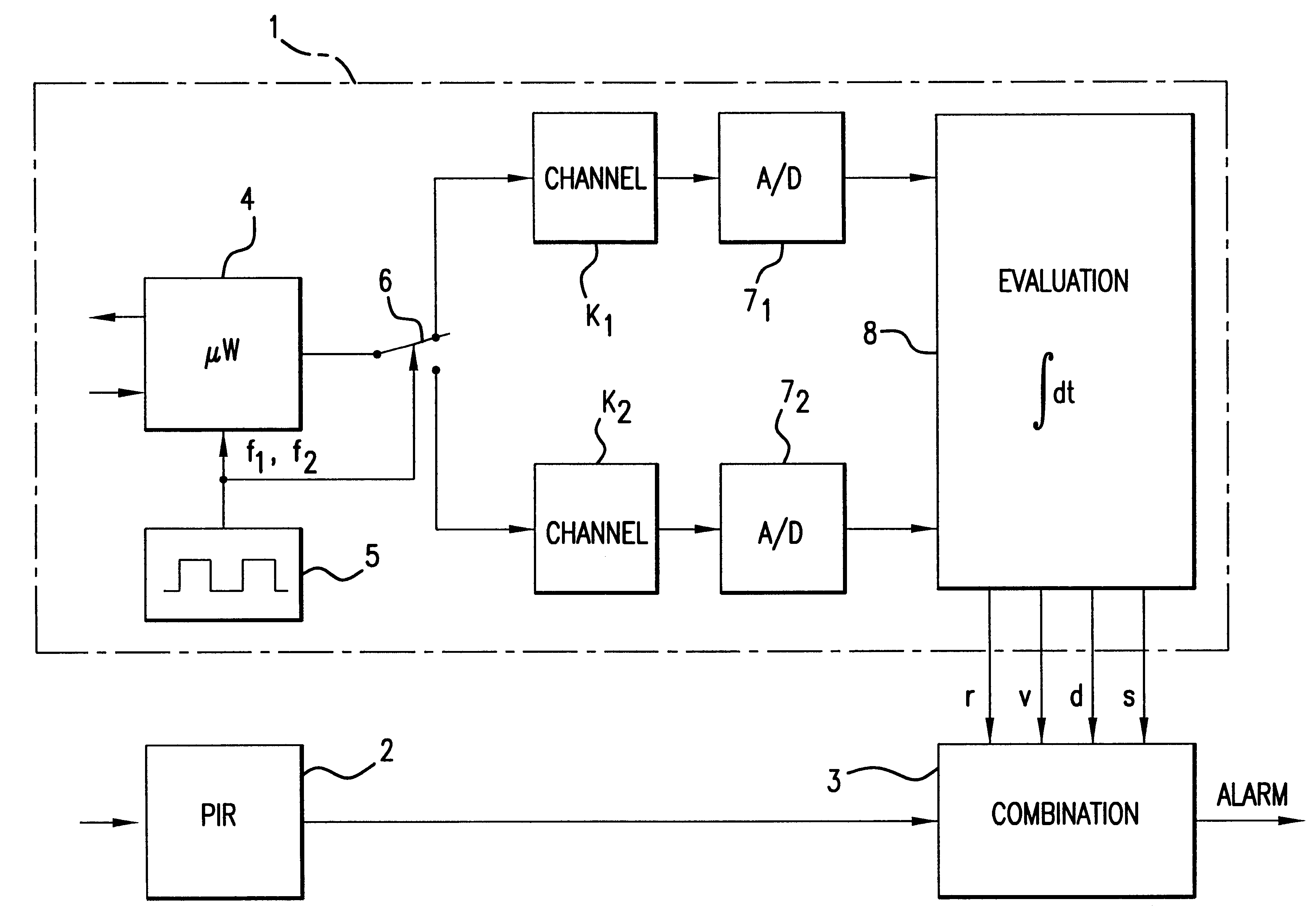
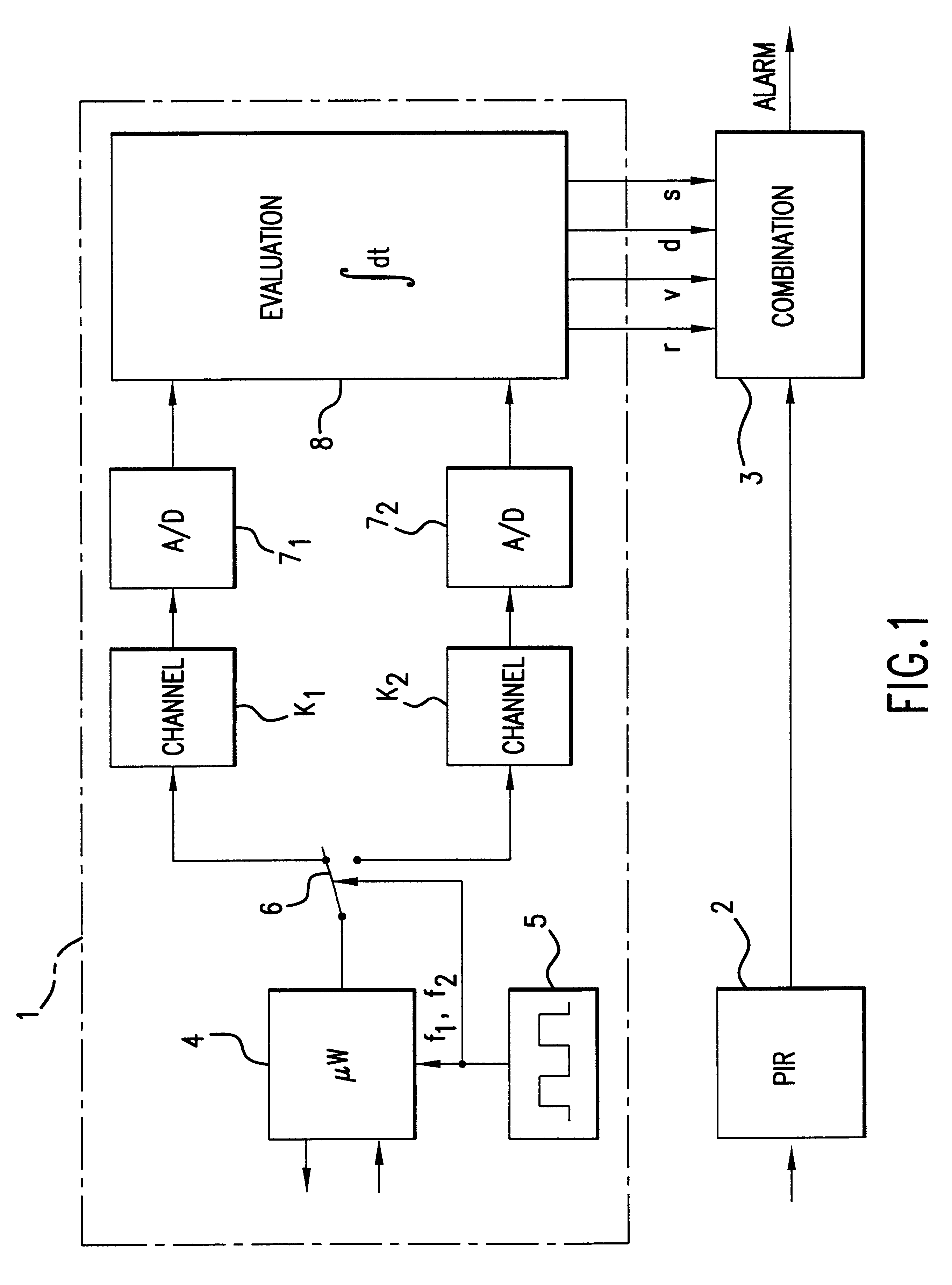
The dual detector shown in FIG. 1 includes a microwave detector 1, a passive infrared detector 2 and a common processing stage 3. At the output of the evaluation stage an alarm signal is obtainable if an unauthorized intruder is present in the room under surveillance monitored by the detector shown. The microwave detector 1 contains a microwave module 4 for emitting and for receiving microwave radiation. Associated with the microwave module 4 is a microwave generator 5 that generates a microwave signal containing at least two frequencies f.sub.1 and f.sub.2 that are fed periodically to the microwave module 4 and to a switch 6 disposed downstream of the latter. The microwave module 4 is periodically switched between the two frequencies f.sub.1 and f.sub.2 and the switch 6 is actuated accordingly. While not shown, the microwave module can preferably emit a number of different frequencies, n. In this case, the switch 6 and generator 5 are adapted to selectively generate these n frequen...


PUM


Abstract

A motion detector based on the Doppler principle contains a microwave module for emitting a microwave signal containing at least two frequencies into a room under surveillance and for receiving the radiation reflected from the latter. An evaluation stage is connected to the microwave module and generates first and second Doppler signals from the received radiation. The first and second Doppler signals have a phase difference which is proportional to the distance of an object reflecting the microwave signal. The phase difference is determined by an integral transformation. In addition, the relative size of an object and the direction of travel of an object reflecting the microwave signal can be determined by the evaluation stage.

Description

The invention relates generally to motion detectors and more particularly relates to a motion detector based on the Doppler principle which employs a microwave module for emitting a microwave signal into a room under surveillance containing at least two frequencies and detecting a phase difference in the signals which is proportional to, inter alia, the distance of an object moving in the room under surveillance.Motion detectors that employ the Doppler principle have a weakness in that small objects, such as, for example, insects or raindrops, situated near the detector can be distinguished only with very great difficulty from further removed, larger objects. As a result, distinguishing distant humans from small domestic animals at a lesser distance and from insects positioned near the detector is made considerably more difficult or even made impossible. In addition, there is the problem that oscillating fixed objects, such as, for example, curtains or leaves moved by the wind or ev...

Claims


Application Information

Patent Timeline
Patent Type & Authority Patents(United States)
IPC IPC(8): G01S13/00G01S13/34G01S13/56G01S13/86
CPCG01S13/348G01S13/56G01S13/86
Inventor HEGNAUER, STEFAN
Owner VANDERBILT INT GMBH
Learn More