
Gray scale fluid ejection system with offset grid patterns of different size spots

a fluid ejection system and gray scale technology, applied in the direction of printing, other printing apparatus, etc., can solve the problems of increasing the complexity and cost of fabrication, and affecting the pattern formation speed

Inactive Publication Date: 2002-04-23
XEROX CORP
View PDF4 Cites 32 Cited by
  • Summary
  • Abstract
  • Description
  • Claims
  • Application Information

AI Technical Summary

Problems solved by technology

A disadvantage of this ejection scheme is that "jaggedness" may be objectionable at edges in the pattern, particularly for lines or curves at small angles to the scan direction as illustrated in FIG. 1.
This, however, increases the complexity and cost of fabrication and typically slows down forming the pattern because of the additional number of spots to be ejected.
These fluid ejectors and methods, however, do not always provide patterns having the desired quality especially when considering fluid density levels, fluid saving modes, and patterns forming throughput.
Therefore, these conventional fluid ejection systems are not capable of forming a pattern using variable fluid density regions.

Method used


Image

  • Gray scale fluid ejection system with offset grid patterns of different size spots
  • Gray scale fluid ejection system with offset grid patterns of different size spots
  • Gray scale fluid ejection system with offset grid patterns of different size spots

Examples


Embodiment Construction

The following detailed description of various exemplary embodiments of the fluid ejection systems according to this invention are directed to one specific type of fluid ejection system, an ink jet printer, for sake of clarity and familiarity. However, it should be appreciated that the principles of this invention, as outlined and / or discussed below, can be equally applied to any known or later developed fluid ejection systems, beyond the ink jet printer specifically discussed herein.

FIG. 3 shows an exemplary carriage-type ink jet printing device 100. One or more linear arrays of droplet-producing channels is housed in one or more printheads 170 mounted on a reciprocal carriage assembly 173. The array extends along the paper advance direction C. In the exemplary carriage-type ink jet printing device 100 shown in FIG. 3, the one or more printheads 170 includes two or more nozzle arrays. Ink droplets 171 are propelled onto a receiving medium 152, such as a sheet of paper, that is stepp...


PUM


Abstract

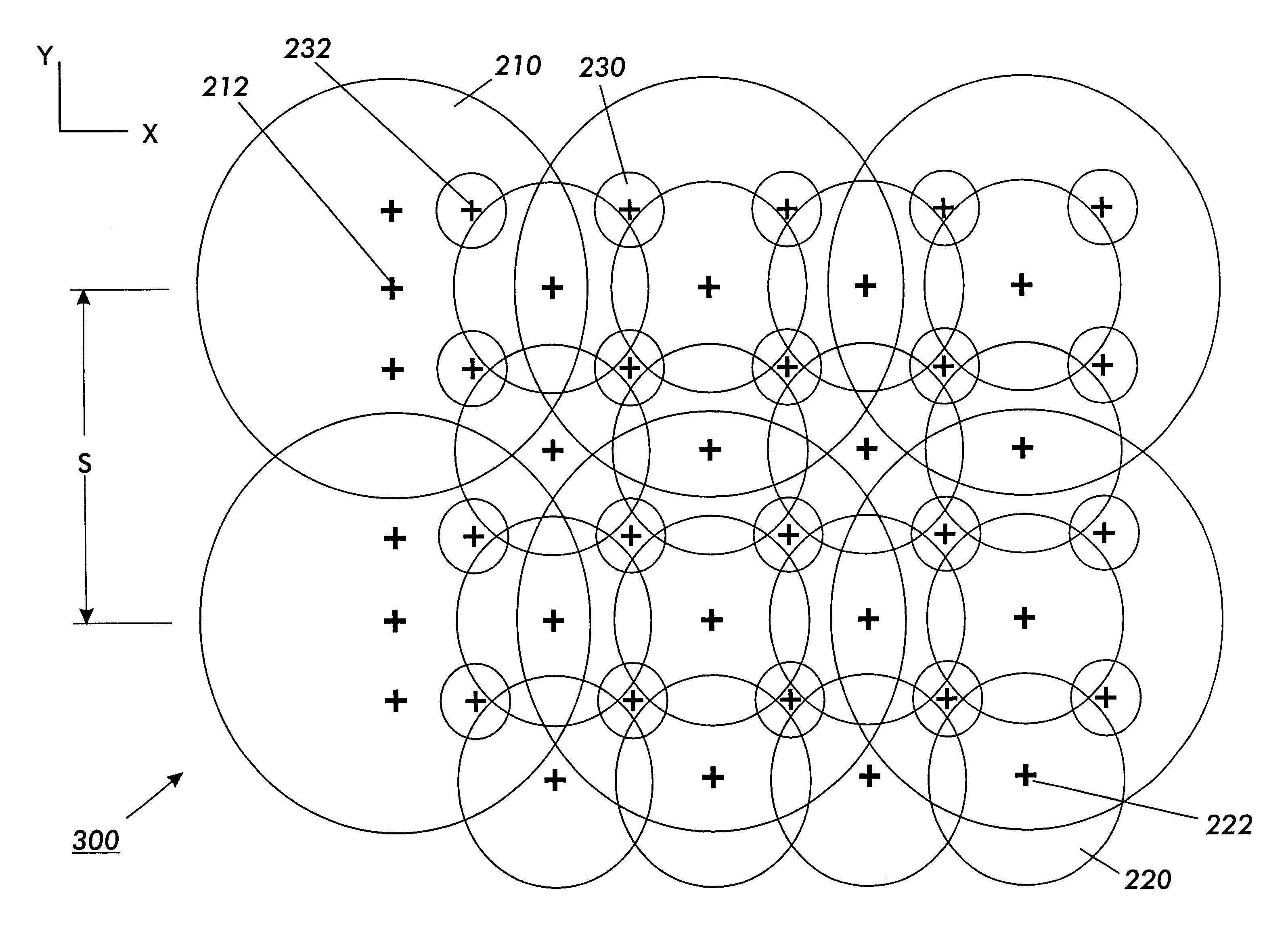
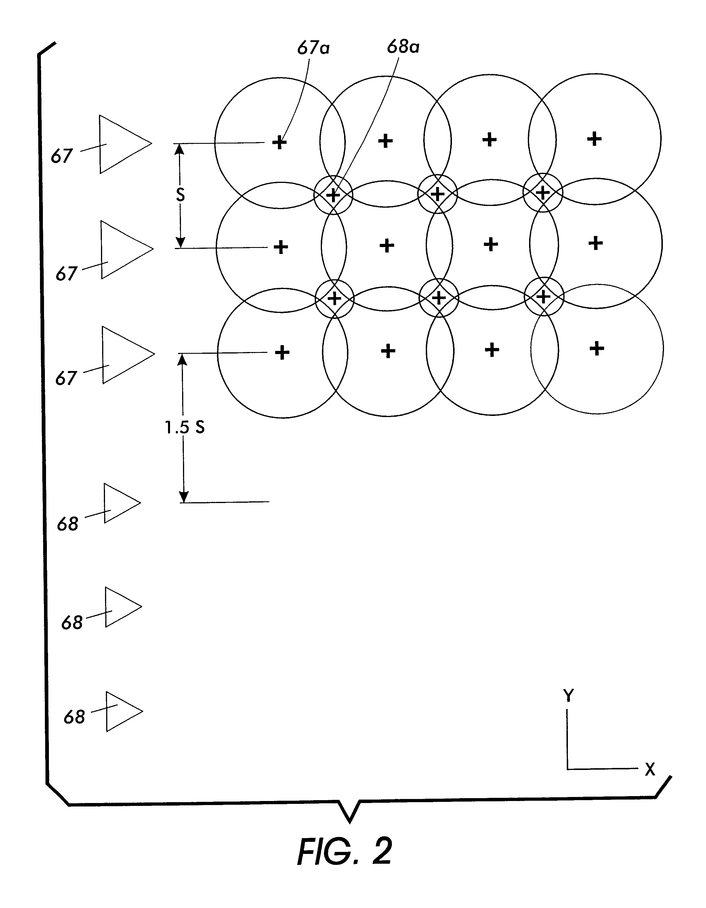
A fluid ejection system and method for variable density pattern forming by producing a plurality of large, mid-sized and small spots. The plurality of large, mid-sized and small spots are produced by a plurality of large, mid-sized and small nozzles, each having a predetermined nozzle diameter. Furthermore, the plurality of large, mid-sized and small spots are placed on different grids, where the grid spacing for at least one of the pluralities of smaller spots is less than the grid spacing of the plurality large spots and is offset from it. The sizes, selection and spacing of the spots are designed to provide a substantially uniformly increasing area coverage from no coverage all the way to full coverage.

Description

1. Field of InventionThis invention relates generally to a liquid ink printing apparatus and a method for gray scale printing using different size drop ejectors.2. Description of Related ArtFluid ejector systems, such as drop-on-demand liquid ink printers, such as piezoelectric, acoustic, phase change wax-based or thermal, have at least one fluid ejector from which droplets of fluid are ejected towards a receiving sheet. Within the fluid ejector, the fluid is contained in a plurality of channels. Power pulses cause the droplets of fluid to be expelled as required from orifices or nozzles at the end of the channels.In a thermal fluid ejection system, the power pulse is usually produced by a heater transducer or resistor, typically associated with one of the channels. Each resistor is individually addressable to heat and vaporize fluid in one of the channels. As voltage is applied across a selected heater resistor, a vapor bubble grows in the associated channel and initially bulges fr...

Claims


Application Information

Patent Timeline
Patent Type & Authority Patents(United States)
IPC IPC(8): B41J2/15B41J2/145B41J2/21B41J2/01B41J2/205
CPCB41J2/2125B41J2/15
Inventor KNEEZEL, GARY ALAN
Owner XEROX CORP
Learn More