Eureka AIR delivers breakthrough ideas for toughest innovation challenges, trusted by R&D personnel around the world.

Sonotrode and anvil energy director grids for narrow/complex ultrasonic welds of improved durability

a technology of ultrasonic welding and energy director, which is applied in the direction of packaging, transportation and packaging, chemistry apparatus and processes, etc., can solve the problems of not revealing a complete vffs or hffs machine, nothing toward maintaining the integrity of the seal, and reducing the cooling requirements. , to achieve the effect of less packaging material and greater durability

Inactive Publication Date: 2016-03-08
RINCO ULTRASONICS USA
View PDF72 Cites 44 Cited by
  • Summary
  • Abstract
  • Description
  • Claims
  • Application Information

AI Technical Summary

Benefits of technology

[0012]It is an object of the invention to provide an improved method for accomplishing packaging using a form-fill-seal machine which is more economical.
[0013]It is another object of the invention to provide improvements to a form-fill-seal machine which reduces material costs of each package.
[0014]It is a further object of the invention to provide a means of improving the ultrasonic welding equipment of form-fill-seal machines to reduce material usage per package.
[0017]It is another object of the invention to provide a narrower ultrasonic weld of greater durability through a sonotrode-anvil combination that causes minor elastic deformation to the work piece prior to welding.
[0019]A specially designed sonotrode and anvil are adapted to be used in combination for ultrasonic welding of work pieces, to produce a narrower weld region, but one exhibiting greater durability, thereby permitting use of less packaging material. The contact surfaces comprise a surface of the anvil having a plurality of energy directors, where the plurality of energy directors are arranged into a three-dimensional grid pattern to selectively distribute vibration-transmissive contact into a three-dimensional contact pattern with the sonotrode. The energy directors, which may serve to increase the total surface area of contact between anvil and sonotrode, may comprise a series of plateau surfaces being regularly spaced apart from each other in a first direction, and in a second direction that is preferably orthogonal to the first direction, to form the grid pattern. The plateau surfaces may each be rectangular-shapes that are oriented at a 45 degree to the weld line, and may have each of the four sides transitioning into an angled side surface, such that the angled side surfaces of adjacent plateaus connect at a trough, and serve to separate the plateau surfaces.

Problems solved by technology

Use of the piezoelectric transducer reduces the cooling requirements, which result from the generation of the heat, which is a byproduct of the friction.
However, Balamuth does not disclose a complete VFFS or HFFS machine.
When a consumer purchases a bag of chips or other product, a significant percentage of the cost of the purchase is attributable to the packaging.
. . ” Similarly, U.S. Pat. No. 4,161,420 to Clarke for “Ultrasonic Method for Manufacturing Brassiere Tapes” taught having an anvil with a knife edge and beveled sections to “provide a comparatively narrow path responsive to the ultrasonic energy applied to the horn.” However, both of these inventions merely teach using a “narrow” anvil / horn combination to produce a narrow width of welded material, but offer nothing toward maintaining the integrity of the seal, which is crucially important for preserving product freshness, and when seeking to securely package liquids.

Method used


Image

  • Sonotrode and anvil energy director grids for narrow/complex ultrasonic welds of improved durability
  • Sonotrode and anvil energy director grids for narrow/complex ultrasonic welds of improved durability
  • Sonotrode and anvil energy director grids for narrow/complex ultrasonic welds of improved durability

Examples


first embodiment

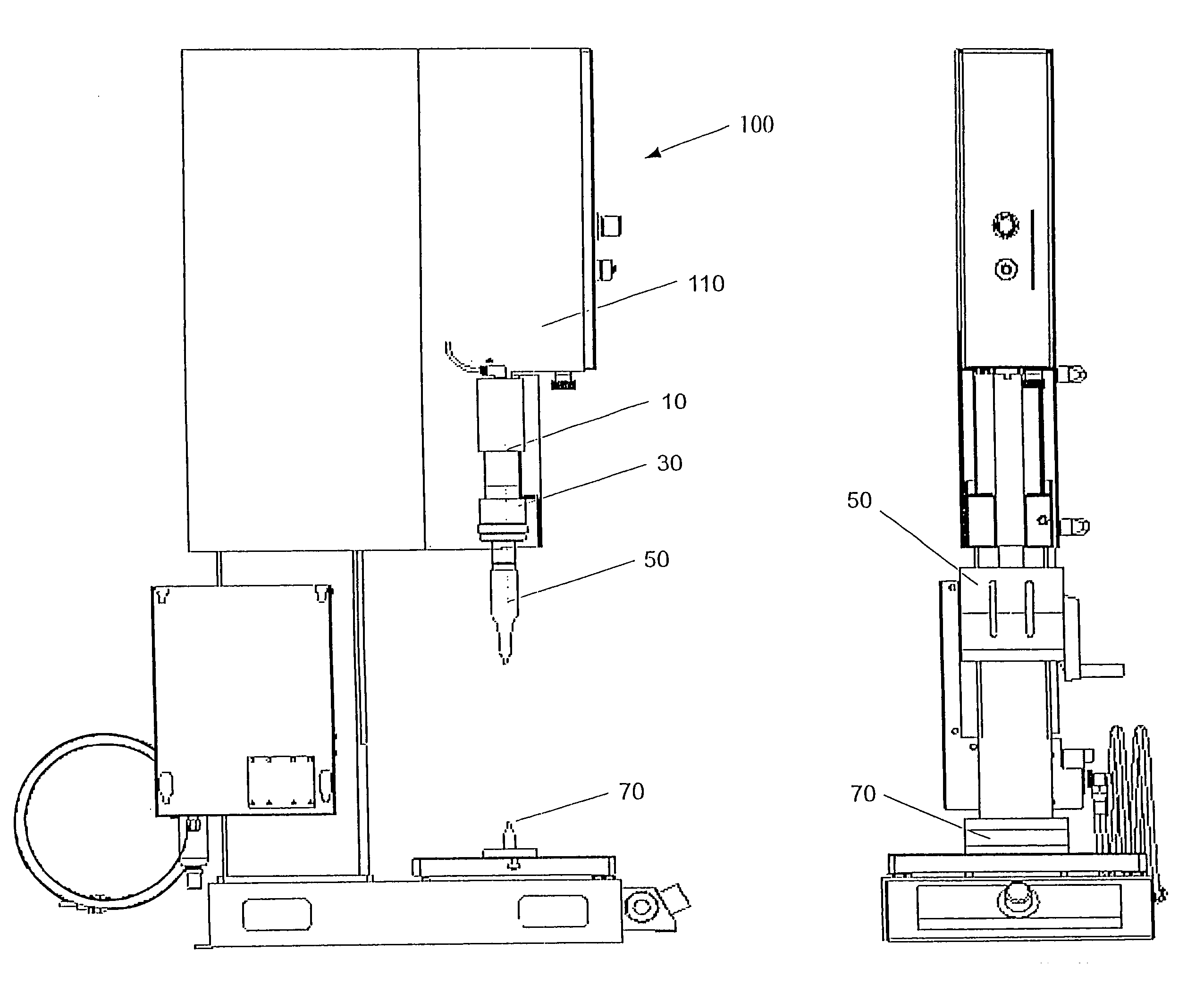
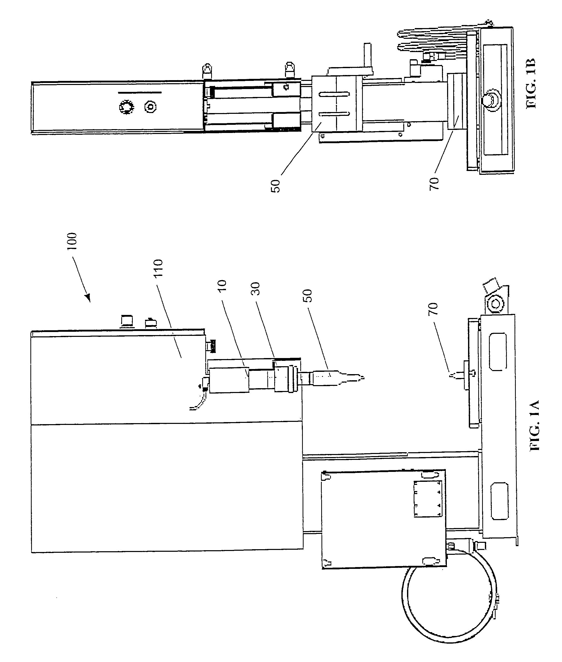
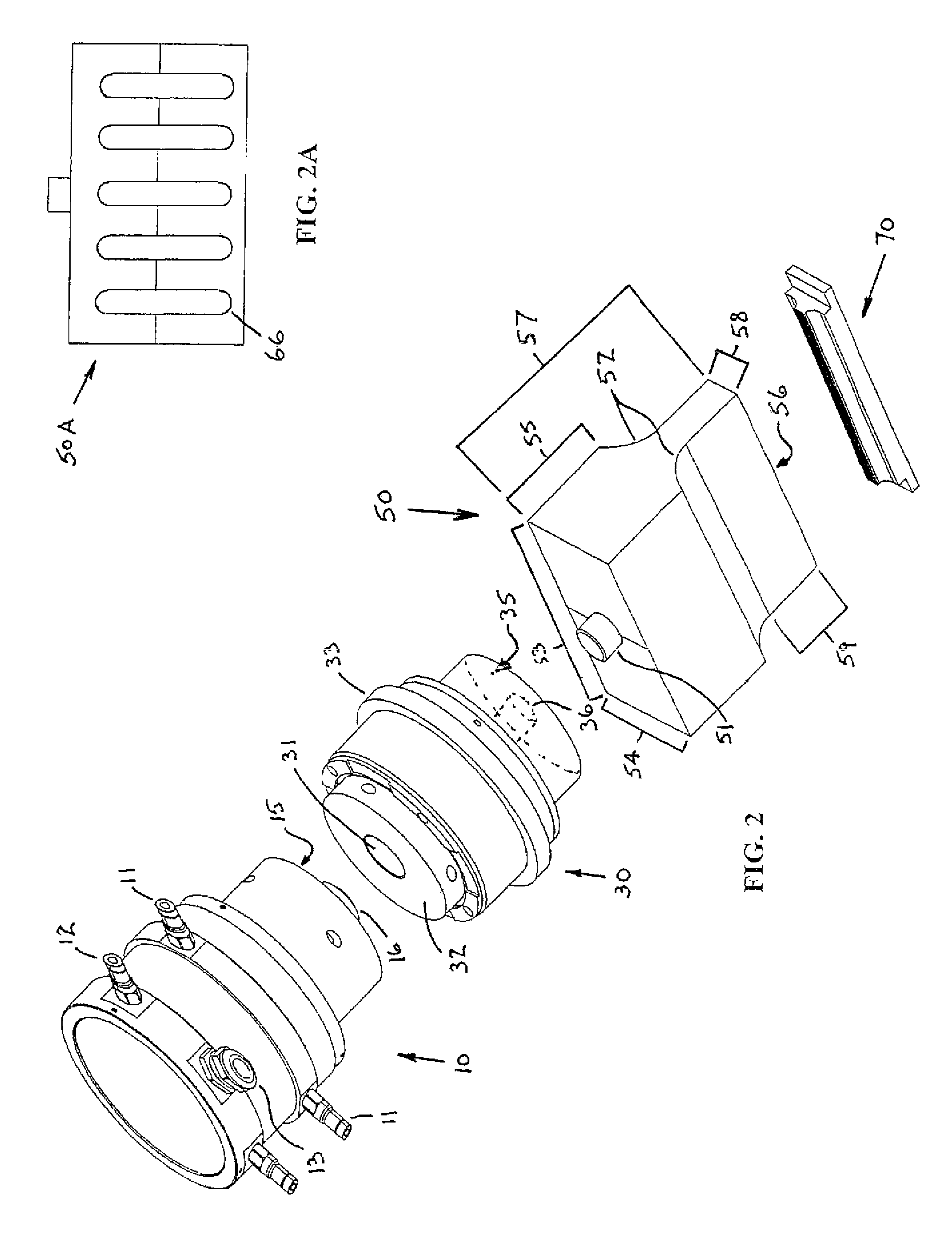
[0059]FIG. 2 shows the present invention, where the stack includes a converter 10, a booster 30, a sonotrode 50, and an anvil 70 that may be used to weld straight patterns. The converter 10 may be comprised of electrical connectors 11, 12, and 13. The converter 10 may also comprise a flat surface 15 from which protrudes a cylindrical connection means 16 that may be received in a corresponding cylindrical opening 31 in flat surface 32 of booster 30, for attachment of the converter to the booster. The booster 30 may have a flange 33 for use in securing the booster to a press. The boaster may have a second flat surface 35 with a cylindrical opening 36 therein, to receive a corresponding cylindrical protrusion 51 of the horn 50. Alternatively, the booster may have a cylindrical protrusion that is received by a cylindrical recess 51A, as seen for the alternative sonotrode 50A of FIG. 1 OA. The cylindrical protrusion 51 of the horn 50 may protrude from a rectangular block, having a length...

second embodiment

[0067]In welding according to the present invention, which is advantageous for thinner work pieces, dramatically improved weld durability is achieved by utilizing alignment between the energy director grids whereby the side surfaces of the sonotrode plateaus interlock with the side surfaces of the anvil plateaus (FIG. 11D) in a repeating 3-dimensional pattern, which may include minor elastic deformation of the work pieces. When the work pieces are inserted between the sonotrode and anvil (FIG. 11C), a three-dimensional weld results. The three-dimensional weld exhibits significantly improved durability over that of conventional ultrasonic welds. Depending on the length of the plateau surface utilized on both the anvil and sonotrode, the surface area of contact may be greater or less than the surface area of contact for flat engagement surfaces of the prior art welding machines. Even where the surface area of contact is somewhat less than that of the prior art flat engagement surfaces...


PUM

PropertyMeasurementUnit
angleaaaaaaaaaa
angleaaaaaaaaaa
frequenciesaaaaaaaaaa

Abstract

A specially designed sonotrode and anvil are adapted to be used in combination for ultrasonic welding of work pieces, to produce a narrower weld region, but one exhibiting greater durability, thereby permitting use of less packaging material. The contact surfaces comprise a surface of the anvil having a plurality of energy directors, where the plurality of energy directors are arranged into a three-dimensional grid pattern to be capable of distributed vibration-transmissive contact. The energy directors may comprise a series of plateau surfaces being regularly spaced apart from each other in a first direction, and in a second direction that is orthogonal to the first direction, to form the grid pattern. The rectangular-shaped plateaus may be spaced apart by valleys. Engagement of the energy directors of the anvil with the corresponding surface of the sonotrode may cause minor elastic deformation of work pieces positioned therebetween prior to ultrasonic welding.

Description

CROSS REFERENCES TO RELATED APPLICATIONS[0001]This application is a continuation of U.S. application Ser. No. 13 / 736,199, filed Jan. 8, 2013, which is a continuation of U.S. application Ser. No. 12 / 925,651 filed Oct. 26, 2010, the disclosures of which are herein incorporated by reference in their entirety.FIELD OF THE INVENTION[0002]The present invention relates to improvements in sonic welding techniques and equipment, and more particularly to apparatus which are capable of sonic welding of films in which the weld areas are narrower for more efficient use of material, but are also more durable.BACKGROUND OF THE INVENTION[0003]There are many products sold today—in supermarkets, mini-marts, vending machines, and in other non-food related retail locations—that require the use of packaging, other than a cardboard box, where the packaging may preferably be flexible and be sealed to be air-tight or liquid-tight. Such packaging is commonly made of a plastic film. Today, such films may typ...

Claims


Application Information

Patent Timeline
Patent Type & Authority Patents(United States)
IPC IPC(8): B32B37/00B29C65/08B29C65/00
CPCB29C66/8141B29C65/08B29C66/0222B29C66/43B29C65/7451B29C66/1122B29C66/244B29C66/3022B29C66/73921B29C66/81427B29C66/81431B29C66/81433B29C66/8167B29C66/8242B29C66/8322B29C66/849B29C66/9516B65B51/225B29C66/9513B29C66/9517B29C66/71B29K2077/00B29K2069/00B29K2067/00B29K2055/02B29K2033/08B29K2027/06B29K2023/12B29K2023/06
Inventor HULL, GORDON
Owner RINCO ULTRASONICS USA
Why Eureka
Eureka Blog
Learn More