
Carbon black and process for producing the same

a technology of carbon black and process, applied in the direction of pigmenting treatment, inorganic chemistry, chemistry apparatus and processes, etc., can solve the problems of aggregation and likely decomposition of sulfate, and achieve the effects of good dispersibility, better dispersibility, and high blackness

Inactive Publication Date: 2002-03-19
MITSUBISHI CHEM CORP
View PDF4 Cites 60 Cited by
  • Summary
  • Abstract
  • Description
  • Claims
  • Application Information

AI Technical Summary

Benefits of technology

The present inventors have analyzed and studied the factors which influence blackness and dispersion behavior of carbon black in matrix, to obtain carbon black having higher blackness and better dispersibility as compared with conventional one. Particularly, they have studied on the method for producing carbon black having blackness equal to or higher than channel black, and having good dispersibility, by a furnace method. As a result, they have found that fine aggregate will be a bad influence on dispersion, and large aggregate will be a bad influence on blackness, and thus carbon black having uniform aggregate free from fine aggregate or large aggregate, has high blackness and good dispersibility. Namely, they have found that carbon black having a small particle size, a small aggregate size and a sharp aggregate size distribution, particularly carbon black free from large aggregate, has high blackness and good dispersibility. Namely, it solves the problems of blackness and dispersibility which are believed to be in an antinomic relation to each other. Further, they have succeeded to directly produce novel carbon black having an average particle size of at most 13 nm, D.sub.mod of at most 80 nm and a D.sub.1 / 2 / D.sub.mod ratio of at most 0.6, by the furnace method, and found that its properties are extremely excellent.
However, in the case where carbon black is oxidized by a various oxidizing agent, even if the amount of the oxidizing agent is increased, or the reaction temperature is raised to accelerate the reaction, the volatile content / N.sub.2 SA ratio increases only to a level of about 0.35 mg / m.sup.2. This is attributable to decrease in carbon black reactive to the oxidizing agents, with the process of the oxidation reaction. This tendency can be observed also in the above-mentioned oxidation method. However, it has been found that increase in the specific surface area due to the reaction for activating carbon black by the oxidizing agents is suppressed, and it is possible to increase the amount of the volatile matter per unit area, the volatile content / N.sub.2 SA ratio, to be exceeding 0.35 mg / m.sup.2, to an extent of 0.50 mg / m.sup.2, by adjusting the nitric acid / carbon black ratio and the residue time in the accompanying air current to be suitable, under the condition where the temperature at the region of the oxidation reaction at which carbon black is oxidized in the accompanying air current, is controlled to be from 120.degree. C. to 200.degree. C. And it has been clarified that carbon black obtained by such a method has a significantly good dispersion stability and optical suitability.

Problems solved by technology

As a result, they have found that fine aggregate will be a bad influence on dispersion, and large aggregate will be a bad influence on blackness, and thus carbon black having uniform aggregate free from fine aggregate or large aggregate, has high blackness and good dispersibility.
Namely, if the pH value is low, there are defects such that when carbon black is mixed with a resin, the resin is likely to decompose, and when carbon black is used as an aqueous coating material, aggregation is likely to take place.

Method used


Image

  • Carbon black and process for producing the same
  • Carbon black and process for producing the same
  • Carbon black and process for producing the same

Examples


examples 10 to 13

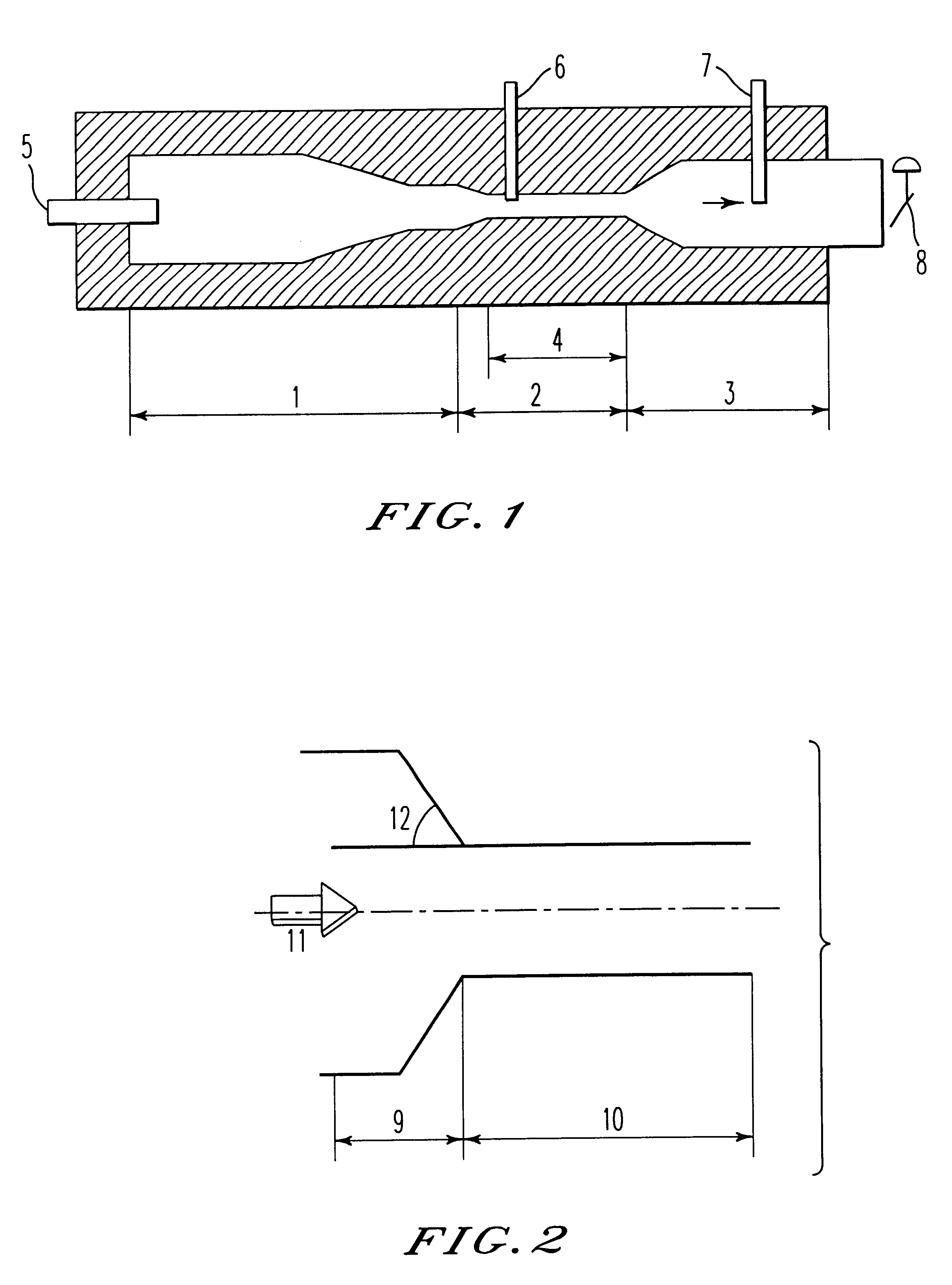
A carbon black producing apparatus was installed which had a structure in which a first reaction zone having an inner diameter of 500 mm and a length of 1400 mm and provided with a duct for introducing air and a combustion burner, a second reaction zone connected from the first reaction zone and comprising a choke part having an inner diameter of 60 mm and a length of 800 mm and having a plurality of feed stock nozzles provided along the circumference, a third reaction zone having an inner diameter of 100 mm and a length of 6000 mm and equipped with a quenching apparatus, and a control valve having a inner valve diameter of 80 mm as a throttle mechanism, were sequentially connected.

example 14

A carbon black producing apparatus, wherein in Examples 10 to 13, the choke part was made to a taper type having an inlet part inner diameter of 50 mm and outlet part inner diameter of 100 mm, was installed.

By using each producing apparatus of above-mentioned Examples 10 to 14, using creosote oil as a fuel and a feed stock, carbon black was produced under conditions shown in Table 5. Various properties of obtained carbon black are shown in Table 6.

To determine analytical characteristic of carbon black produced by the present invention, the above-described testing methods were employed.

examples 15 to 18

A carbon black producing furnace, of which the scheme is shown in FIG. 1, was installed which had a structure in which a first reaction zone provided with a duct for introducing air and a combustion burner, a second reaction zone connected from the first reaction zone and comprising a choke part having a inner diameter of 60 mm and a length of 1000 mm and having a plurality of feed stock nozzles provided along the circumference, and a third reaction zone having an inner diameter of 100 mm and a length of 6000 mm and equipped with a quenching apparatus, were sequentially connected.

The part of the material nozzle was 100 mm away from the inlet of the choke part.

By using the above-mentioned furnace, carbon black having properties shown in Table 7 was produced by adjusting the combustion gas temperature at the part of introducing the feed stock, the oxygen concentration in the combustion gas and the amount of feed stock supplied. Creosote oil was used as the fuel and the feed stock. Oxy...


PUM


Abstract

A carbon black having an average particle size of at most 13 nm, Dmod of at most 80 nm, a D½ / Dmod ratio of at most 0.6 and at least pH 5.

Description

The present invention relates to carbon black which is useful for various applications such as a filling material, a reinforcing material, an electroconductive material or a coloring pigment, and an effective method for its production to control physical properties thereof.Carbon black has been widely used as a pigment, a filler, a reinforcing pigment or a weather resistance-improving agent. As a method for its production, a furnace type production method by using a cylindrical carbon black producing furnace is widely known wherein in a first reaction zone, an oxygen-containing gas and a fuel are introduced in the furnace axis direction or in the tangent direction; while a high temperature combustion gas stream obtained by burning them is moved to a second reaction zone provided downstream to the first reaction zone in the furnace axis direction, a feed stock is introduced to the gas stream to form a carbon black; and the reaction gas is quenched to terminate the reaction in a third...

Claims


Application Information

Patent Timeline
IPC IPC(8): C09C1/50C09C1/44
CPCC09C1/50C01P2004/64C01P2006/10
Inventor OMAE, YOSHIHIROMISE, NOBUTAKEFUKUYAMA, YUTAKASEKINE, YUUICHIYAMAMOTO, TAKAHARUTAKEHARA, HIROAKIYAMAGUCHI, TSUYOSHINAKAJIMA, SUSUMUISHIDA, MASANOBUNAKAYAMA, MAMORUMAEDA, HIROSHI
Owner MITSUBISHI CHEM CORP
Learn More