
Dual cone loudspeaker

a dual-cone, loudspeaker technology, applied in the direction of transducer diaphragms, instruments, electrical transducers, etc., can solve the problems of short life span of the speaker, fatigue and ultimate failure of adhesive or other techniques for bonding the ends of the radial spokes to the bobbin, and achieve reliable construction, extended frequency range, and improved linkage

Inactive Publication Date: 2002-01-29
COFFIN C RONALD
View PDF36 Cites 51 Cited by
  • Summary
  • Abstract
  • Description
  • Claims
  • Application Information

AI Technical Summary

Benefits of technology

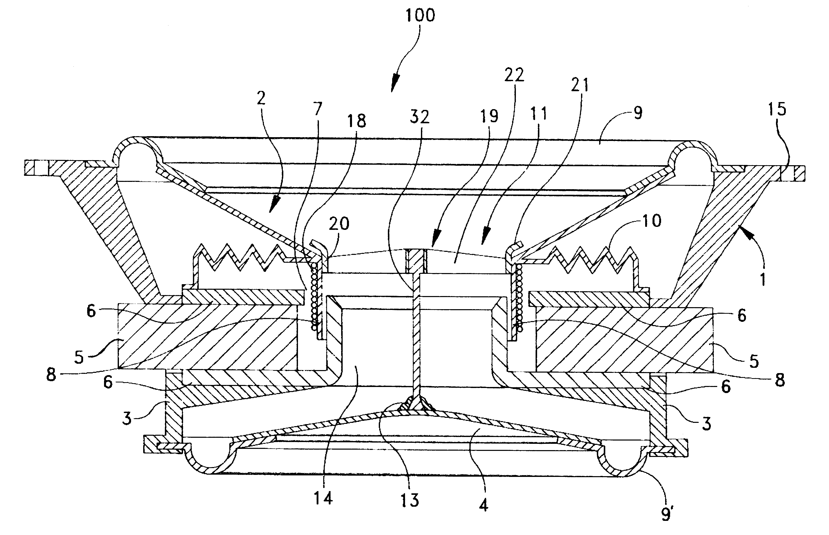
Therefore it is an object of this invention to provide a dual cone loudspeaker with an improved linkage between the primary and secondary speaker cones.
Still another object of this invention is to provide improved linkage that enables a coupled dual cone loudspeaker to operate over an extended frequency range.

Problems solved by technology

However, it is difficult to attach these outer ends of the radial spokes to the speaker cone or bobbin without distorting the voice coil.
Moreover, adhesive or other techniques for bonding the ends of the radial spokes to the bobbin are subject to fatigue and ultimate failure.
Stress concentrations at attachment points tend to force the bobbin out of round in operation contributing to a short life span for the speaker.
It has also been found that this speaker is limited to operation at lower frequencies as a bass speaker.

Method used


Image

  • Dual cone loudspeaker
  • Dual cone loudspeaker
  • Dual cone loudspeaker

Examples


embodiment 102

FIG. 5 depicts another embodiment 102 of a loudspeaker with an improved bass response modified to provide an enhanced high frequency response. In this embodiment the center portion of the secondary speaker cone 4 is replaced with a stiff high frequency radiator 50 attached to the annular speaker cone 4 by a surround 51. An attachment 13 as described in the other embodiments connects the high frequency radiator 50 to a rigid coupling device 52 carried by the open support structure 19. This rigid coupling device 52 includes a piezoelectric transducer 53 attached to the spokes 22 and hub and energized by a separate source (not shown). A rigid member 54 attaches to the output of piezoelectric transducer 53 and the attachment 13.

At low frequencies, the rigid coupling device 52 moves the primary speaker cone 2 in the same manner as occurs in the embodiments of FIGS. 1 and 4. The piezoelectric transducer 53 only receives high frequency signals from a crossover, phase or other adjustment ne...

embodiment 104

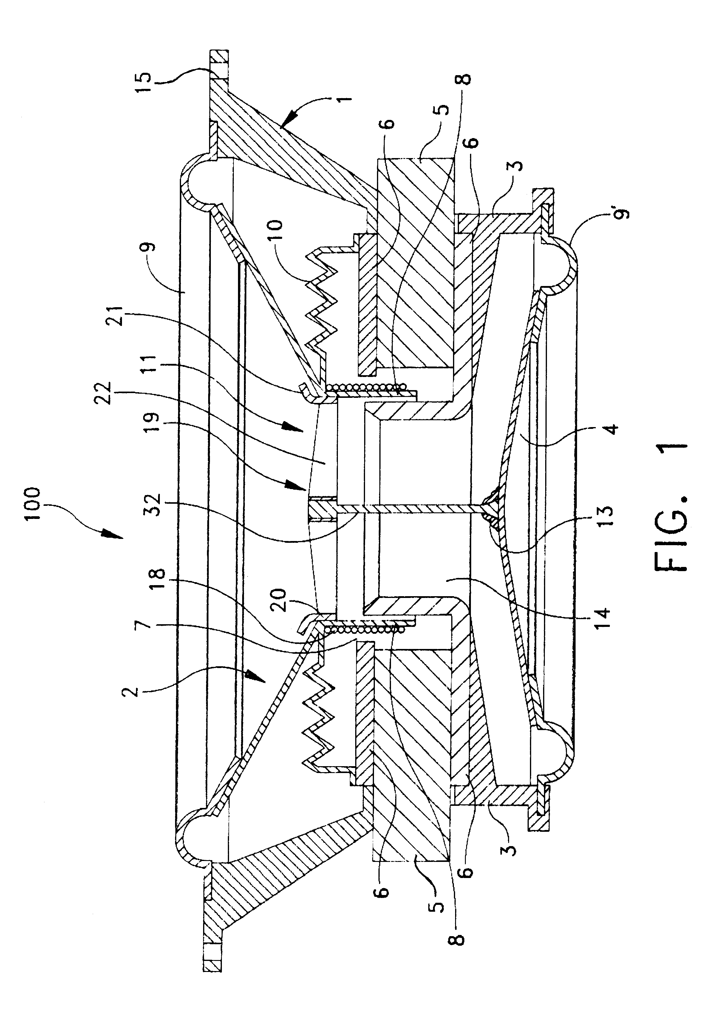
FIGS. 7 through 10 depict still another loudspeaker embodiment having the same general construction as shown in FIGS. 1 and 4 through 6. Referring specifically to FIG. 7, this loudspeaker embodiment 104 includes a rigid frame 1 that carries a primary speaker cone 2. A subframe 3 carries a secondary speaker cone 4. Both the first and second cones 2 and 4 are annular in shape. A surround 9 connects the primary speaker cone 2 to the frame 1. A surround 9' connects the second annular speaker cone 4 to the subframe 3. A permanent magnet 5 with pole pieces 6 defines an air gap 7 for a voice coil 18. The pole pieces 6 also form a passage or orifice 14 from the chamber formed by the subframe 3 and second speaker cone 4 through the primary speaker cone 2.

In this embodiment the connection between the primary speaker cone 2 and the second cone 4 is constituted by a rigid link 70 that has three basic components. These include a cylindrical section 71, a circular section 72 and a rigid element 7...


PUM


Abstract

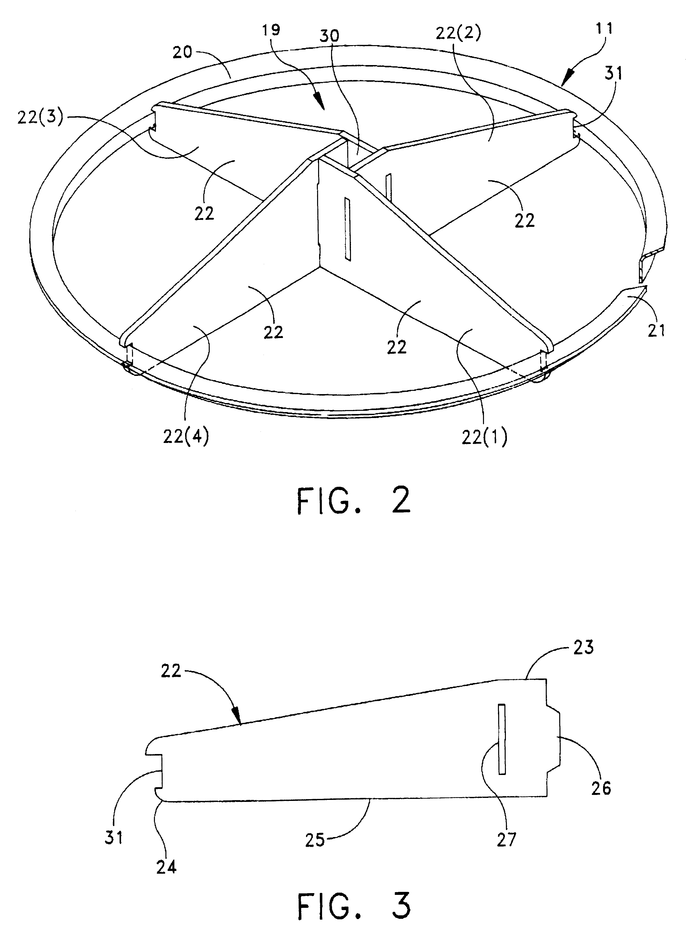
A dual-cone loudspeaker includes a primary speaker cone and an axially displaced secondary speaker cone mounted to the back of a magnet structure. A rigid link causes both cones to move in unison. The rigid link includes an open support structure with equiangularly extending spokes that form a central hub. A ring circumscribes the spokes and ataches to the first speaker cone. A rigid element connects to the spokes and the secondary speaker cone so the primary and secondary speaker cones move in unison and improve the bass response for the loudspeaker. The rigid coupling device is also adapted to support a high frequency radiator to extend the overall loudspeaker frequency response into higher frequencies.

Description

BACKGROUND OF THE INVENTION1. Field of the InventionThis invention generally relates to acoustical loudspeakers and more particularly to acoustical loudspeakers with improved bass response.2. Description of Related ArtMy U.S. Pat. No. 4,595,801 discloses a dual cone loudspeaker with a primary speaker cone similar in function to a conventional dynamic loudspeaker mounted on a frame with a magnet structure. A secondary speaker cone mounts to a subframe on the back of the magnet structure and connects to the primary speaker cone through a rigid coupling device so the primary and secondary speaker cones move in unison. Sound waves from the secondary speaker cone travel through an orifice in a center pole piece of the magnet structure and through a hole in the center of the primary speaker cone radiating in the same direction as sound waves from the primary speaker cone. Consequently for a given excursion of the primary speaker cone my dual cone structure generates a sound having a great...

Claims


Application Information

Patent Timeline
IPC IPC(8): H04R9/00H04R9/06
CPCH04R9/06
Inventor COFFIN, C. RONALD
Owner COFFIN C RONALD
Learn More