
Parallel mechanism

a parallel mechanism and degreeoffreedom technology, applied in the field of multi-degreeoffreedom (dof) parallel mechanisms, can solve the problems of large load being applied to the elbow and shoulder actuators, inherently plagued serial mechanisms, and compromising the overall performance of the mechanical system

Inactive Publication Date: 2001-12-18
MOORE RUSSELL
View PDF11 Cites 424 Cited by
  • Summary
  • Abstract
  • Description
  • Claims
  • Application Information

AI Technical Summary

Benefits of technology

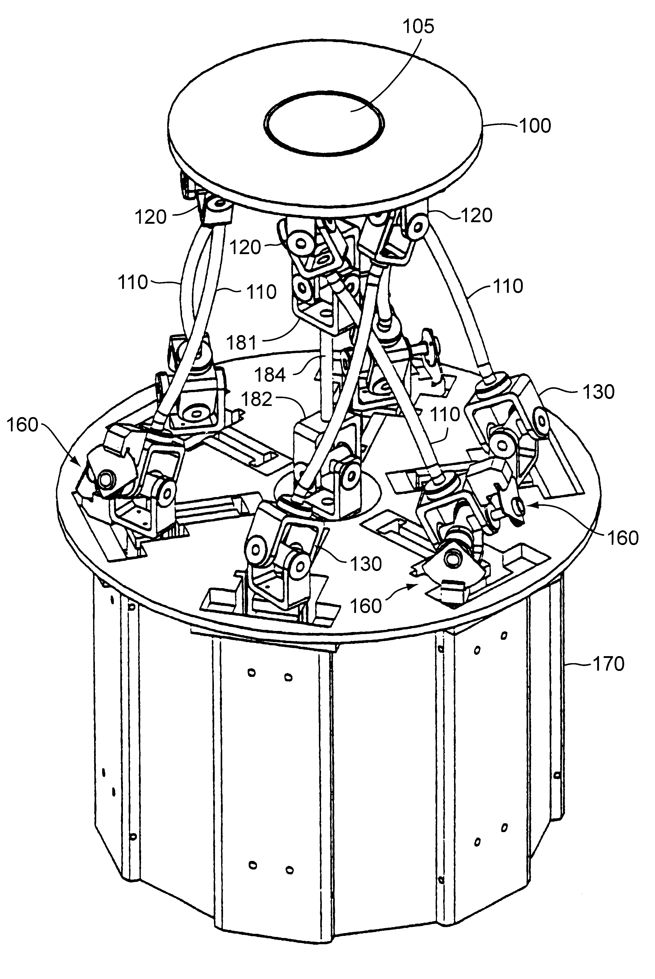
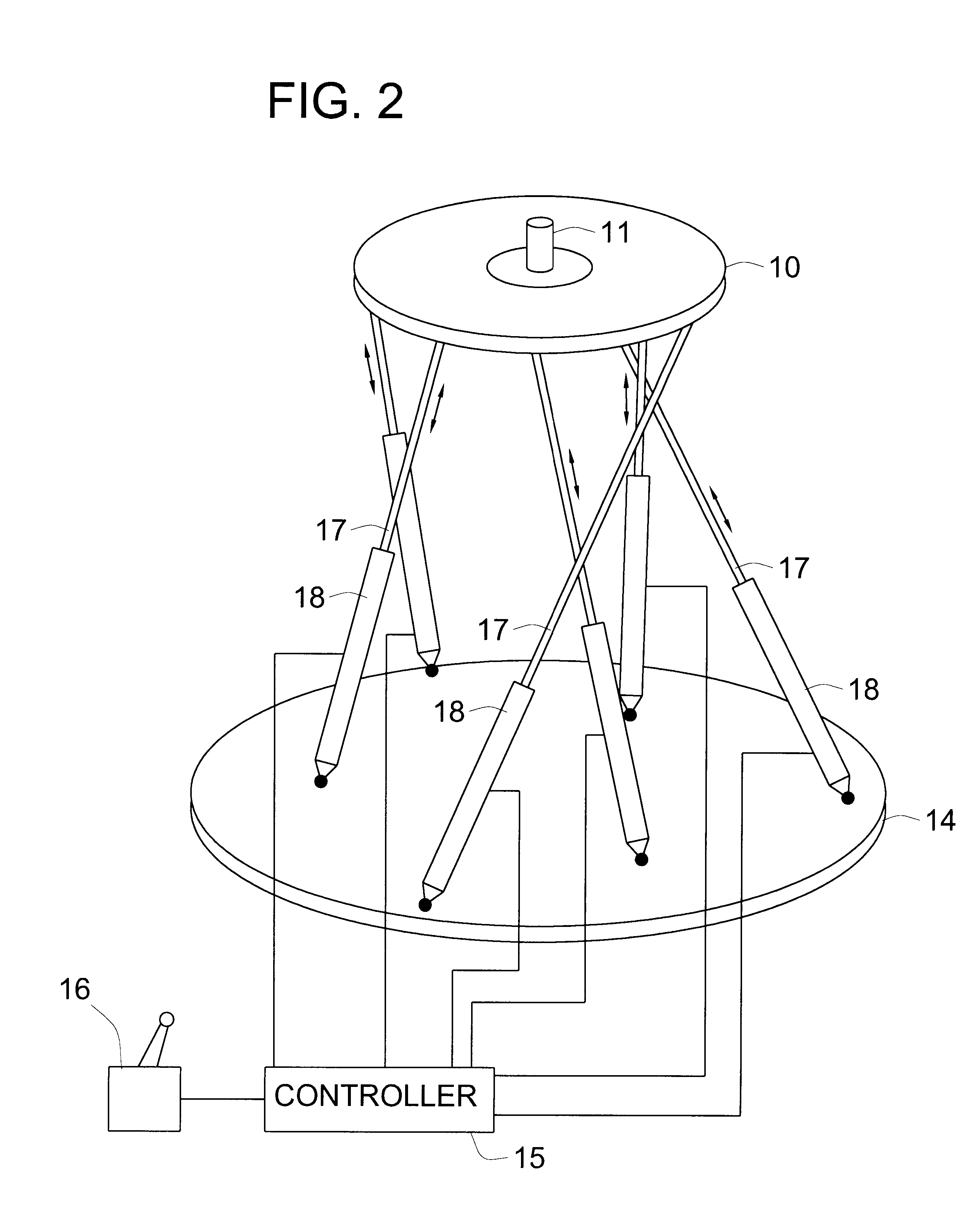
According to one form of the present invention, a parallel mechanism for manipulating an object includes a platform for supporting an object to be manipulated, a plurality of links each having a first end rotatably connected to the platform and a second end spaced from the platform with the platform being kinematically restrained by the links, and a plurality of linear motors each associated with one of the links for translating the first end of the corresponding link to move the platform. The use of linear motors to translate the links enables smooth, precise control of the movement of the mechanism and / or the force exerted by the mechanism, making it highly suitable for use in the assembly or manipulation of delicate objects. Linear motors also help to give the mechanism a low inertia, which is highly advantageous from the standpoint of speed and accuracy of control.
According to another form of the present invention, a parallel mechanism for manipulating an object includes a platform for supporting an object to be manipulated, a plurality of links each having a first end rotatably connected to the platform and a second end spaced from the platform with the platform being kinematically restrained by the links, an actuator associated with each link for translating the first ends of the links to move the platform, and a rotatable support member rotatably mounted on the platform for supporting an object to be manipulated. In preferred embodiments, the rotatable support member comprises a rotatable tool plate mounted on the platform. The support member is preferably rotated by a drive member which is spaced from the platform and coupled to the support member in a manner enabling the drive member to rotate the support member with respect to the platform at varying angles and positions of the platform relative to the drive member. The rotatable support member enables an object supported by it to be rotated by a greater amount and at a faster speed than is possible by movement of the links alone. Furthermore, the support member can prevent an object supported by it from rotating while the rotational position of the platform is adjusted.
According to yet another form of the present invention, a parallel mechanism includes a plurality of links connected to a platform for supporting an object to be manipulated with the platform being kinematically restrained by the links, with at least one of the links being a nonlinear link having a portion not coinciding with a straight line between its first and second ends. Nonlinear links increase the range of movement of the platform before links interfere with each other, resulting in a larger workspace for the mechanism, as well as the ability to employ link geometries giving the mechanism high dexterity.
According to still another form of the present invention, a parallel mechanism includes six links having first and second rotatable joints at its opposite ends, with the first joints connecting the links to a platform for supporting an object to be manipulated and with the platform being kinematically restrained by the links. The centers of rotation of the first joints are spaced at substantially equal angular intervals about a first axis, and the centers of rotation of the second joints are spaced at substantially equal angular intervals about a second axis when the mechanism is in a reference position. Having the joints equally spaced about the axes results in high dexterity, meaning that the mechanism can apply roughly the same forces and moments in any direction and enables the mechanism to be as compact as possible.
A parallel mechanism according to the present invention is capable of having a high mechanical bandwidth, a low inertia, a high dexterity, and low frictional resistance, all of which combine to enable it to operate with a high degree of position and force control unattainable by conventional serial or parallel mechanisms.
The end platform of a parallel mechanism according to the present invention can be used to support a medical device, such as a diagnostic device or a surgical tool. Because the links and the end platform can be made extremely small, the mechanism can be used either for surgery through a large surgical opening or for endosurgery through a small surgical opening or body orifice. Because the end platform is capable of being manipulated with high accuracy and dexterity and can provide force feedback to the user, the parallel mechanism is particularly suitable for use in surgery by remote control. The ability of the mechanism to adjust the position of the end platform with a resolution on the order of nanometers makes the mechanism highly suitable for medical applications requiring precise, fine motions, and particularly for microsurgery performed with the aid of a microscope, including eye surgery, ear, nose and throat surgery, neurosurgery, and micro-hand or micro-orthopedic surgery.

Problems solved by technology

It has been shown that the forward kinematic problem is always directly solvable for serial mechanisms.
Despite the above mentioned advantages, serial mechanisms are inherently plagued with a number of disadvantages.
With a serial mechanism, having an actuator close to the object being driven compromises the overall performance of the mechanical system, since actuators are typically heavy electric motors.
The former choice allows precise control of the wrist but also requires that elbow and shoulder actuators located closer to the base support these wrist actuators, resulting in a large load being applied to the elbow and shoulder actuators.
The latter choice reduces the moving mass which the elbow and shoulder actuators of the robot must support, but it also introduces numerous potential sources of error in the control of the position and / or force of the wrist, including backlash, friction, and wear.
Another problem of serial mechanisms occurs when the position of the mechanism remote from a support structure is determined by sensors, such as encoders, which are located at the joints of the mechanism and measure the angles between adjoining links.
Errors in measurement by the encoders are cumulative, i.e., the error in the calculated position of the remote end of the mechanism is a sum of errors of the individual encoders, so it is difficult to determine the position of the remote end with accuracy.
Even when there is no encoder error, calculation of the position of the remote end may be inaccurate due to bending of the links forming the serial mechanism.
These problems occur not just with robotic wrists but with serial mechanisms in general.
In spite of such advantages, parallel mechanisms have not achieved widespread acceptance as robotic or teleoperated devices due to a number of drawbacks.
One is that conventional parallel mechanisms have limited reachable workspaces compared to serial mechanisms, so they are limited to tasks which do not require large workspaces.
This is in part because parallel mechanisms have multiple mechanical ties to a fixed support structure whereas serial mechanisms have only one, and in part because the parallel links of a parallel mechanism can interfere with one another in certain positions.
In addition, the forward kinematics problem for a parallel mechanism can be extremely complex mathematically, and in many cases it is not solvable, often making real time control of a parallel mechanism difficult or impossible.
Aside from the above problems, both parallel and serial mechanisms of conventional design tend to suffer from backlash in the components, relatively high friction, a narrow operational bandwidth, and high inertia which make high positional resolution and highly sensitive force control difficult to achieve.
Nonlinear links increase the range of movement of the platform before links interfere with each other, resulting in a larger workspace for the mechanism, as well as the ability to employ link geometries giving the mechanism high dexterity.

Method used


Image

  • Parallel mechanism
  • Parallel mechanism
  • Parallel mechanism

Examples


Embodiment Construction

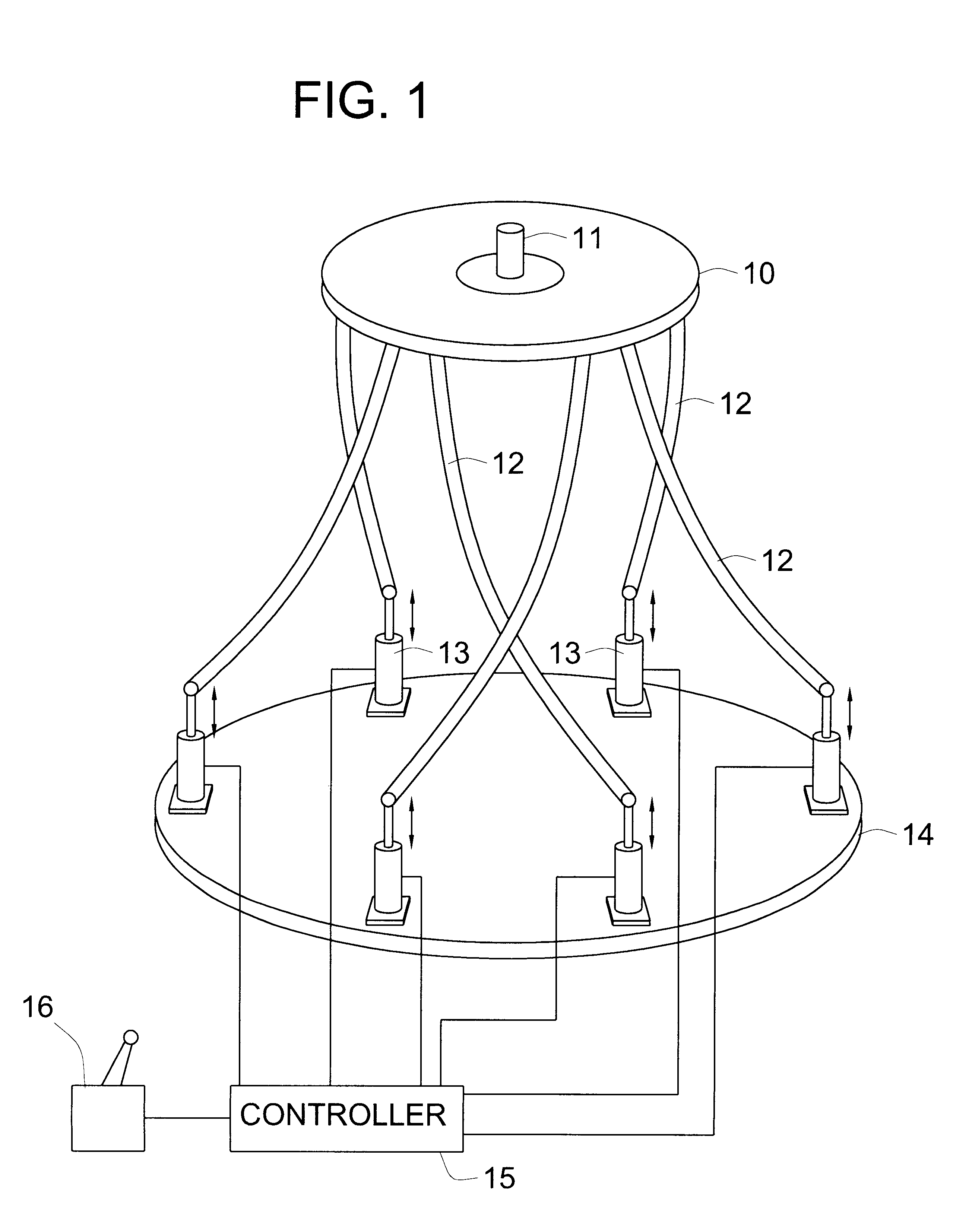
FIG. 1 schematically illustrates an embodiment of a parallel mechanism according to the present invention. This embodiment includes an end platform 10 which can be used to support and manipulate a load 11, such as a tool, a sensor, a workpiece, or any other member which it is desired to support and manipulate in space. The end platform 10 is in turn supported by a plurality of links 12, each of which has a first end pivotably connected to the end platform 10 and a second end pivotably connected to an actuator 13 which is capable of translating the second end and exerting a force on the end platform 10 through the link 12. The actuators 13 are supported atop a suitable support member 14, which may be a stationary member, such as a rigid base or table, or it may be a movable member, such as a robotic arm. The actuators 13 are controlled by a controller 15 which controls the operation of the actuators 13 either autonomously to enable the mechanism to function as an autonomous robot, or...


PUM


Abstract

A parallel mechanism is capable of positioning and orienting an end platform with up to six or more degrees of freedom. In preferred embodiments, the mechanism includes six links having a first and second ends. The first end is connected to an end platform for supporting a tool, while the second end is connected to an actuator capable of translating the second end. A rotational drive mechanism may be provided for rotating an object mounted on the end platform at varying orientations of the end platform independently of movement of the end platform as a whole. The links may be curved in order to avoid interference between adjoining links, thereby permitting an increased range of motion and improved dexterity of the mechanism.

Description

1. Field of the InventionThe present invention relates to multiple degree-of-freedom (DOF) parallel mechanisms which can provide quick and precise manipulative capabilities.2. Description of the Related ArtThe vast majority of multiple degree-of-freedom mechanisms that are used in robotic or teleoperator applications are so-called serial mechanisms. A serial mechanism is one in which a plurality of links are connected together in series to form an open chain and are moved with respect to each other by actuators connected between them to manipulate an object supported at the remote end of the chain of links. This type of mechanical mechanism has the advantages of the ability to access large workspaces, and of simplicity of design and geometric analysis. It has been shown that the forward kinematic problem is always directly solvable for serial mechanisms. The forward kinematic problem is defined as the task of solving for the position and orientation of the remote end of the mechanis...

Claims


Application Information

Patent Timeline
Patent Type & Authority Patents(United States)
IPC IPC(8): A61B19/00B25J17/02B25J11/00
CPCA61B19/22B25J11/00B25J17/0266A61B2019/2226A61B2019/2234A61B2019/2242Y10T74/20335A61B2019/464A61B2019/2296A61B34/70A61B34/71A61B34/77A61B2034/304A61B2034/305A61B2090/064
Inventor CHARLES, STEVE T.STOUGHTON, ROBERT S.
Owner MOORE RUSSELL
Learn More