
Architecture and method of coupling electromagnetic energy to thermal detectors

a thermal detector and electromagnetic energy technology, applied in the field of radiation sensors, can solve problems such as difficulty in achieving and maintaining an efficient

Inactive Publication Date: 2001-12-11
HRL LAB +1
View PDF1 Cites 134 Cited by
  • Summary
  • Abstract
  • Description
  • Claims
  • Application Information

AI Technical Summary

Problems solved by technology

However, a problem associated with conventional microbolometer architectures involving thermally isolated detectors is the difficulty in achieving and maintaining an efficient coupling of some bands of electromagnetic radiation, such as millimeterwave (mm-wave) and microwave radiation, to a thermal detector and, in particular, to an array of thermal detectors, while maintaining the thermal isolation of the detector(s) needed for high sensitivity.

Method used


Image

  • Architecture and method of coupling electromagnetic energy to thermal detectors
  • Architecture and method of coupling electromagnetic energy to thermal detectors
  • Architecture and method of coupling electromagnetic energy to thermal detectors

Examples


Embodiment Construction

Illustrative embodiments and exemplary applications will now be described with reference to the accompanying drawings to disclose the advantageous teachings of the present invention.

While the present invention is described herein with reference to illustrative embodiments for particular applications, it should be understood that the invention is not limited thereto. Those having ordinary skill in the art and access to the teachings provided herein will recognize additional modifications, applications, and embodiments within the scope thereof and additional fields in which the present invention would be of significant utility.

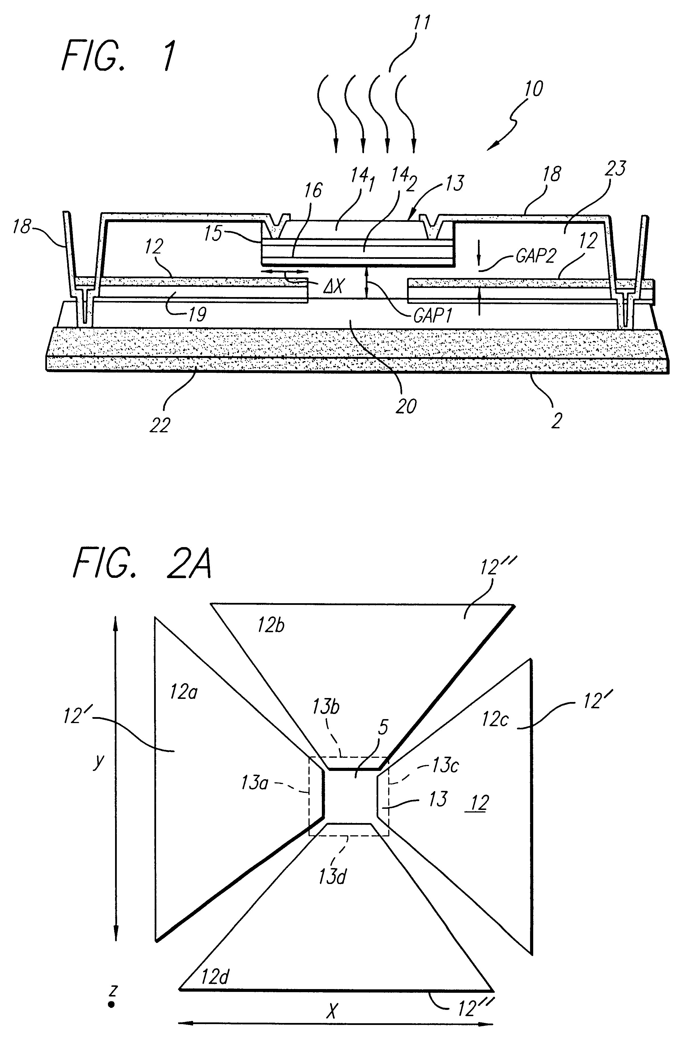
General speaking, the present invention provides efficient coupling of electromagnetic radiation (e.g., millimeter radiation) to a thermal detector, and, in particular, to an array of thermal detectors while maintaining the thermal isolation of the thermal detector as needed for high sensitivity. The embodiments of this invention use a thermally isolated microbr...


PUM


Abstract

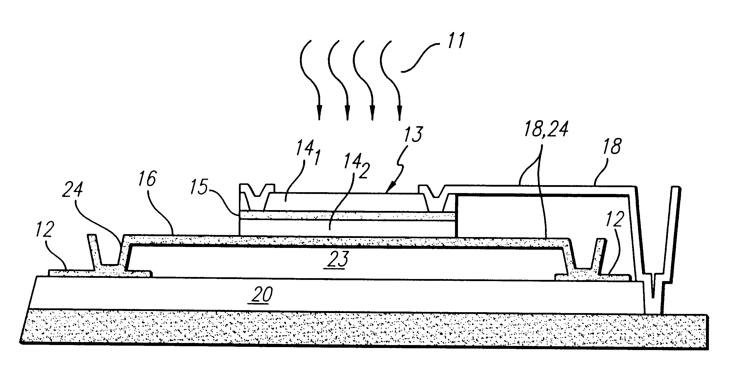
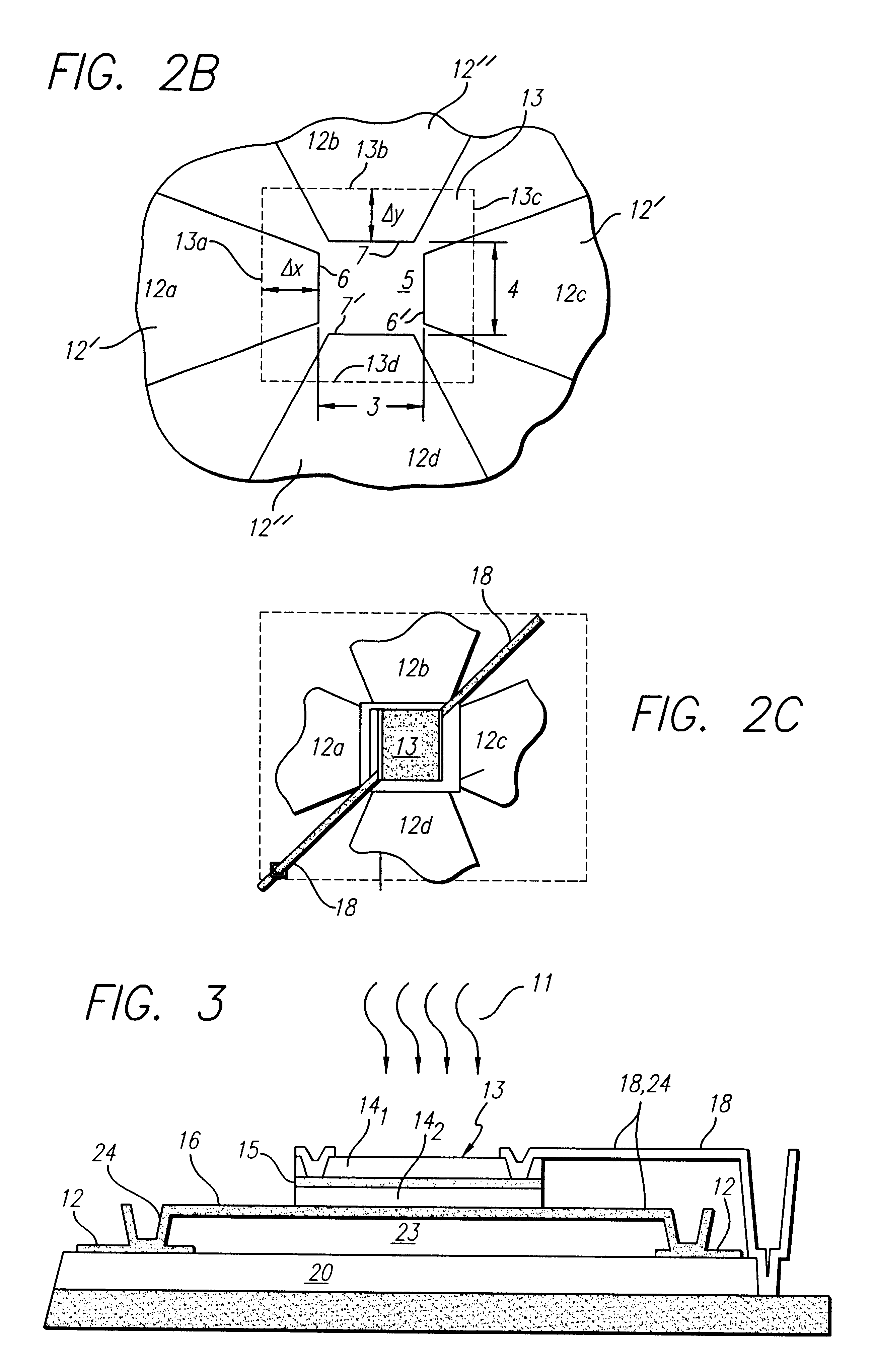
A radiation sensor. The inventive sensor has a two-level detector structure formed on a substrate in which a thermal detector element is suspended over the substrate as a microbridge structure. A receiver of electromagnetic radiation is provided on the same side of the substrate in a manner that efficiently couples the radiation field to the thermal detector element. The thermal detector element has a sandwich structure including a heater metal layer, a dielectric layer, and a thin film thermo-resistive material. The thermal detector element is suspended out of physical contact with the receiver. In one embodiment, the receiver is an antenna having a crossed bowtie configuration that efficiently couples the radiation field to the detector element. The inventive radiation sensors are especially useful for mm-wave and microwave sensing applications. The sensor can be used individually or in linear or two-dimensional arrays thereof. The invention also is directed to a method of fabricating such a radiation sensor.

Description

1. Field of the InventionThe present invention generally relates to the field of radiation sensors. More particularly, the present invention relates to high sensitivity electromagnetic radiation sensors useful as passive imagers in the millimeter wave or microwave regimes.2. Description of the Related ArtRadiation sensors are generally known which convert electromagnetic radiation energy absorbed by a radiation sensitive material into an electrical signal. Conventional thermal detection has included temperature sensitive capacitors or temperature sensitive resistors (also called bolometers) arranged in an array where a detector signal is coupled into a signal multiplexer. The amount of radiation received by a thermal detector is relatively small, which is critical, particularly when the detector is an uncooled type, and measures have had to be taken to decrease the heat capacity of the detector and prevent dissipation of the received radiation. To accomplish this, the prior art has ...

Claims


Application Information

Patent Timeline
Patent Type & Authority Patents(United States)
IPC IPC(8): G01J5/20H01Q9/28H01Q1/22H01Q9/04H01Q21/24
CPCG01J5/02G01J5/023G01J5/08G01J5/0837G01J5/20H01Q1/22H01Q9/28H01Q21/24
Inventor JACK, MICHAEL D.RAY, MICHAELVARESI, JOHNGRINBERG, JANFETTERMAN, HAROLDDOLEZAL, FRANKLIN A.
Owner HRL LAB
Learn More