
Method of forming a tubular blank into a structural component and die therefor

a technology of structural components and tubular blanks, which is applied in the direction of shaping tools, furnaces, heat treatment apparatuses, etc., can solve the problems of inability to use the die members used in plastic blow forming for forming steel, large equipment to direct high pressure liquid into the tubular blanks, and short life of die members, so as to enhance the mechanical properties of the resulting structural components and quick expansion of the blanks

Inactive Publication Date: 2001-11-27
TEMPER IP
View PDF8 Cites 79 Cited by
  • Summary
  • Abstract
  • Description
  • Claims
  • Application Information

AI Technical Summary

Benefits of technology

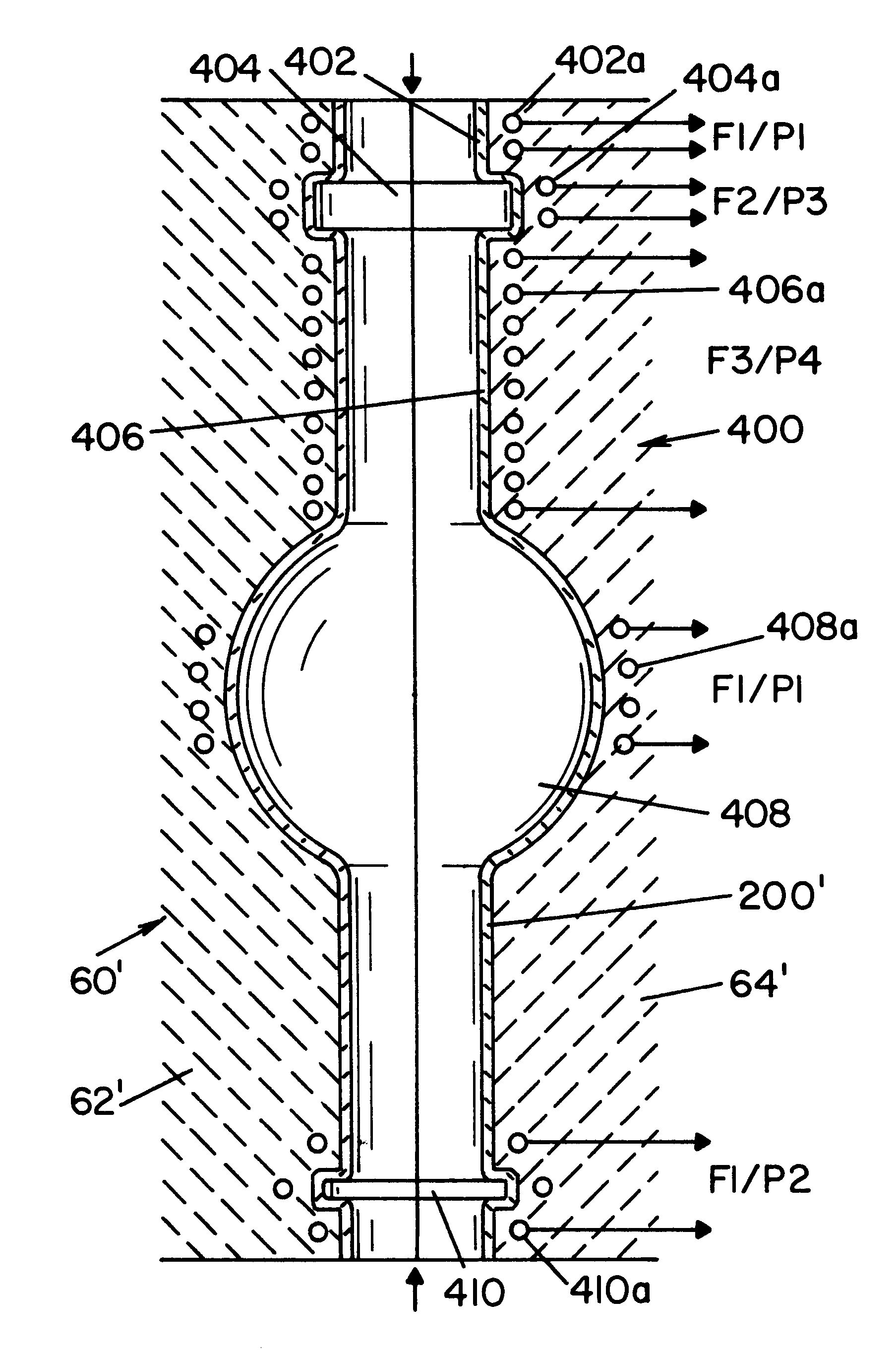
The present invention provides a completely different type of technology which is dissimilar to hydroforming of steel and blow forming of plastic sheets. In accordance with the present invention, a tube is made from sheet metal formed by controlled rolling of the sheet. The sheet metal is formed into a tubular blank which is preheated using resistance electric heating and preformed to the desired axial profile. The preheated blank is placed into the shell or cavity of a specially constructed die set in which are embedded induction heating conductors or coils spaced axially along the cavity. The tubular blank has an open end or open ends which are plugged or sealed. The tubular blank is expanded by high inert gas at a pressure in the general range of 100-5,000 psi, but preferably in the range of 200-1000 psi. During expansion, the induction heating conductors or coils induce an A.C. voltage into the metal of the blank which cause I.sup.2 R heating of the blank. Consequently, the blank can be rapidly expanded. The cavity or shell having the desired predetermined shape surrounds the expanding tube to impart, to the outer surface of the blank the shape of the shell or cavity. The structural element is then cooled at a controlled quenching rate to control the metallurgical characteristics to enhance the mechanical properties of the resulting structural components.
Still a further object of the present invention is the provision of a die set for practicing the method as defined above, which die set includes a shell or cavity formed from a hard, rigid ceramic supported by a non-magnetic cast fill material so the shell has long life and the fill material has high compressive force characteristics.

Problems solved by technology

The equipment to direct high pressure liquid into the tubular blank is extremely large and expensive.
In addition, the die members are expensive machined parts and have a short life.
Hydroforming operations have a general limitation that they are used primarily for bending of the tubular blank, since the steel being formed is processed at ambient temperature which limits the maximum strain rate for the metal being formed.
Even though there are process limitations in using hydroforming to make tubular structural components, a substantial technology field has developed around this process.
Of course, such die members used in plastic blow forming can not be used for forming steel.
The highly developed technology of hydroforming of steel tubes and blow forming of plastic sheets are background of the present invention, but are not economically usable for forming sheet steel tubular blanks into tubular structural components.
In addition, these prior processes do not have the capability of controlling the metallurgical characteristics along the length of the tubular blank, as obtainable by the present invention.
The Boeing Company process is not background information from the standpoint that it is not capable of forming a tubular metal blank into a structural tubular component and is not capable of controlling the metallurgical characteristics of the metal forming the structural tubular component.

Method used


Image

  • Method of forming a tubular blank into a structural component and die therefor
  • Method of forming a tubular blank into a structural component and die therefor
  • Method of forming a tubular blank into a structural component and die therefor

Examples


Embodiment Construction

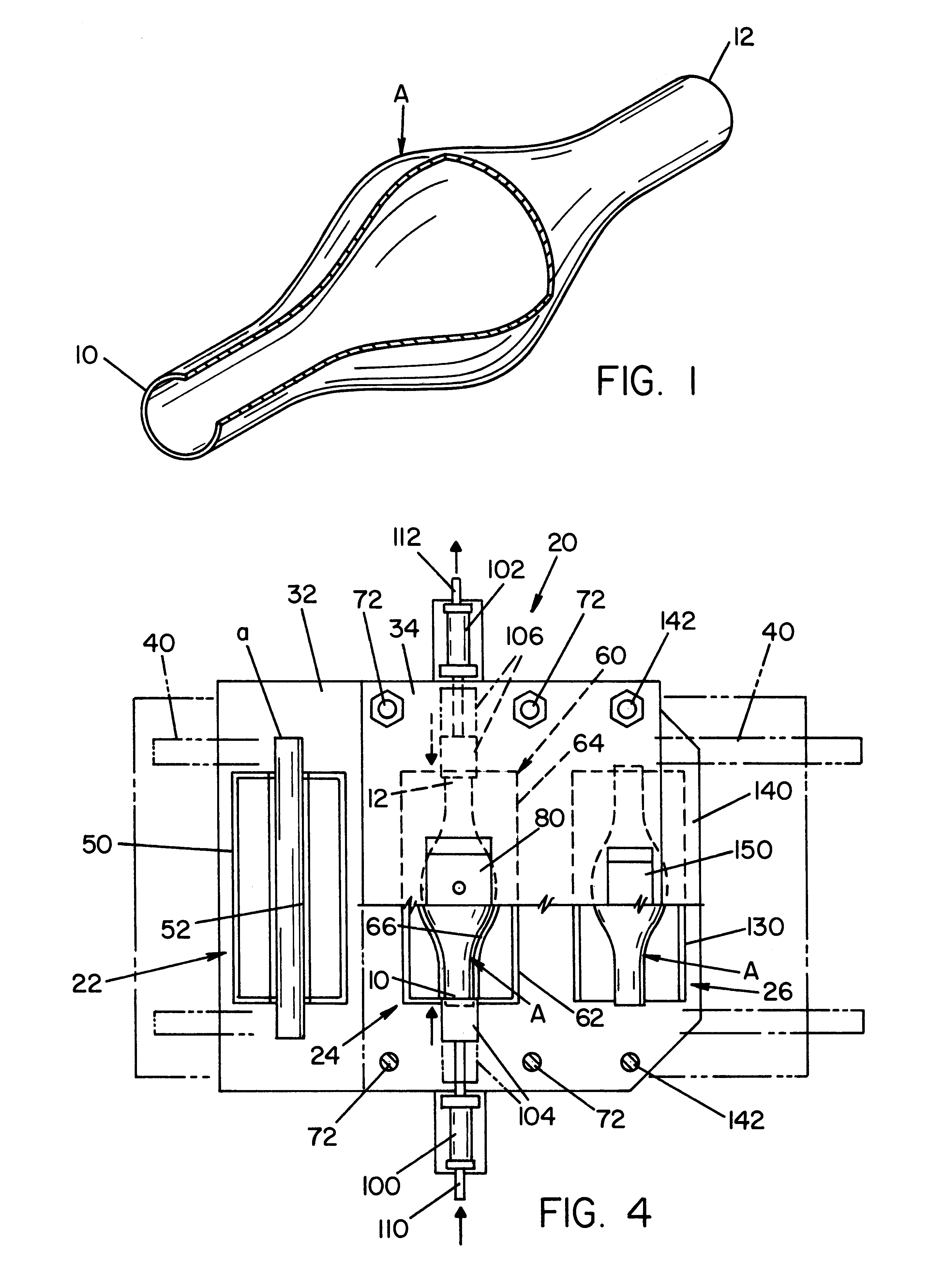
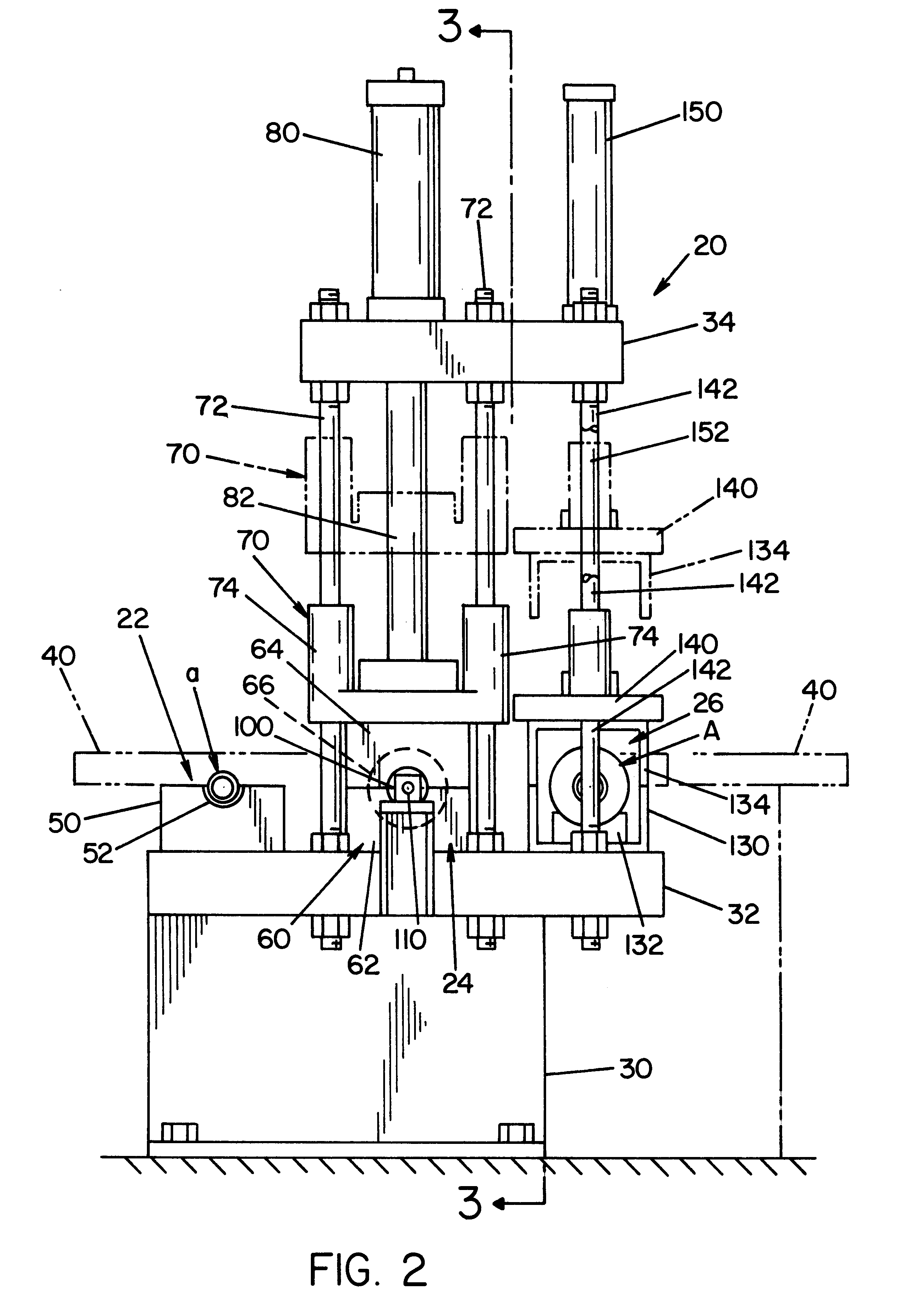
Referring now to the drawings wherein the showings are for the purpose of illustrating the preferred embodiments only and not for the purpose of limiting same, FIG. 1 shows a finished tubular structural component A formed by using the preferred embodiment of the present invention as schematically illustrated as machine 20 in FIGS. 2-4. This part is illustrated as a quite simple shape for ease of discussion. The preferred shape is the workpiece processed by the apparatus shown in FIGS. 22-26. However the disclosure associated with the simple shape of component A applies to all shapes. Machine 20 includes an inlet station 22 for preprocessing a plugged tubular blank which will be described later. This preforming operation may involve bending the tubular blank axially into a preselected general contour or profile as shown in FIG. 22 for the preferred workpiece formed by the invention. The preprocessing of tubular workpiece or blank may involve preforming or heating. Preheating is used ...


PUM

PropertyMeasurementUnit
pressureaaaaaaaaaa
pressureaaaaaaaaaa
pressureaaaaaaaaaa

Abstract

A method of forming an elongated tubular blank into a tubular structural component having a predetermined outer configuration, the method comprising: providing a shape imparting shell formed from a low permeability, rigid material which includes an inner surface defining the predetermined shape, plugging the open ends of the tubular blank, placing the plugged blank into the shell, and forming the tubular blank into the tubular component by inductively heating axial portions of the blank by axially spaced conductors adjacent the shell while or before forcing gas at a high pressure into the plugged blank until the blank conforms to at least a portion of the inner surface of the shell to form the structural component.

Description

The present invention relates to the art of forming structural components such as used in motor vehicles and more particularly to a method of forming a tubular blank into a structural component by use of high pressure inert gas.INCORPORATION BY REFERENCEThe invention involves formation of tubular metal components of structural type as used in automotive support frame where a tubular blank is formed to match the shape defined by the inner surface of a shell or cavity. In accordance with the invention, the shell or cavity is in a low permeability cast support structure wherein induction heating coils are embedded for inductively heating the tubular blank preparatory to formation into the desired shape imparted by the shell or cavity. A similar technology has been developed by Boeing Company wherein a flat plate is formed against a contoured wall by gas pressure. This process is referred to as superplastic forming of the plate and is disclosed in Gregg U.S. Pat. No. 5,410,132, incorpor...

Claims


Application Information

Patent Timeline
Patent Type & Authority Patents(United States)
IPC IPC(8): B21D26/02B21D26/00A61F13/15B21D26/033B21D26/039B21D26/041B21D26/043B21D26/045B21D26/055B21D26/059B21D53/88
CPCA61F13/15203B21D26/033B21D26/039B21D26/041B21D26/043B21D26/055B21D26/059B21D37/16B21D53/88B21D26/045A61F2013/1539Y10T29/49805Y10S72/709
Inventor DYKSTRA, WILLIAM C.PFAFFMANN, GEORGE D.WU, XIN
Owner TEMPER IP
Learn More