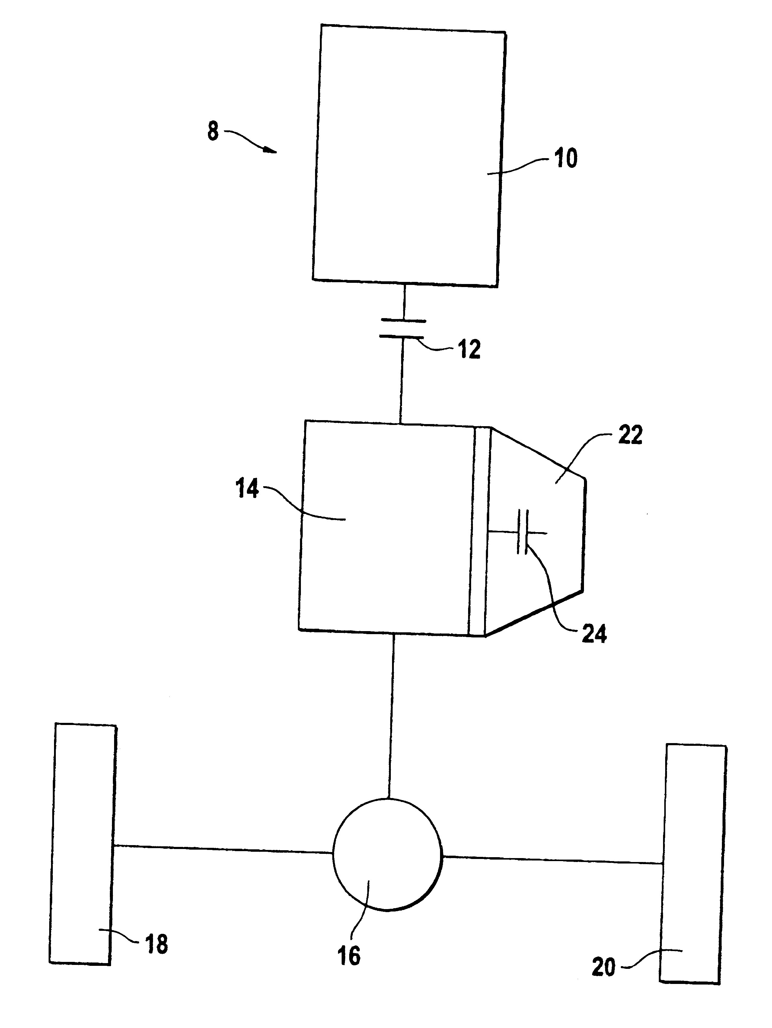
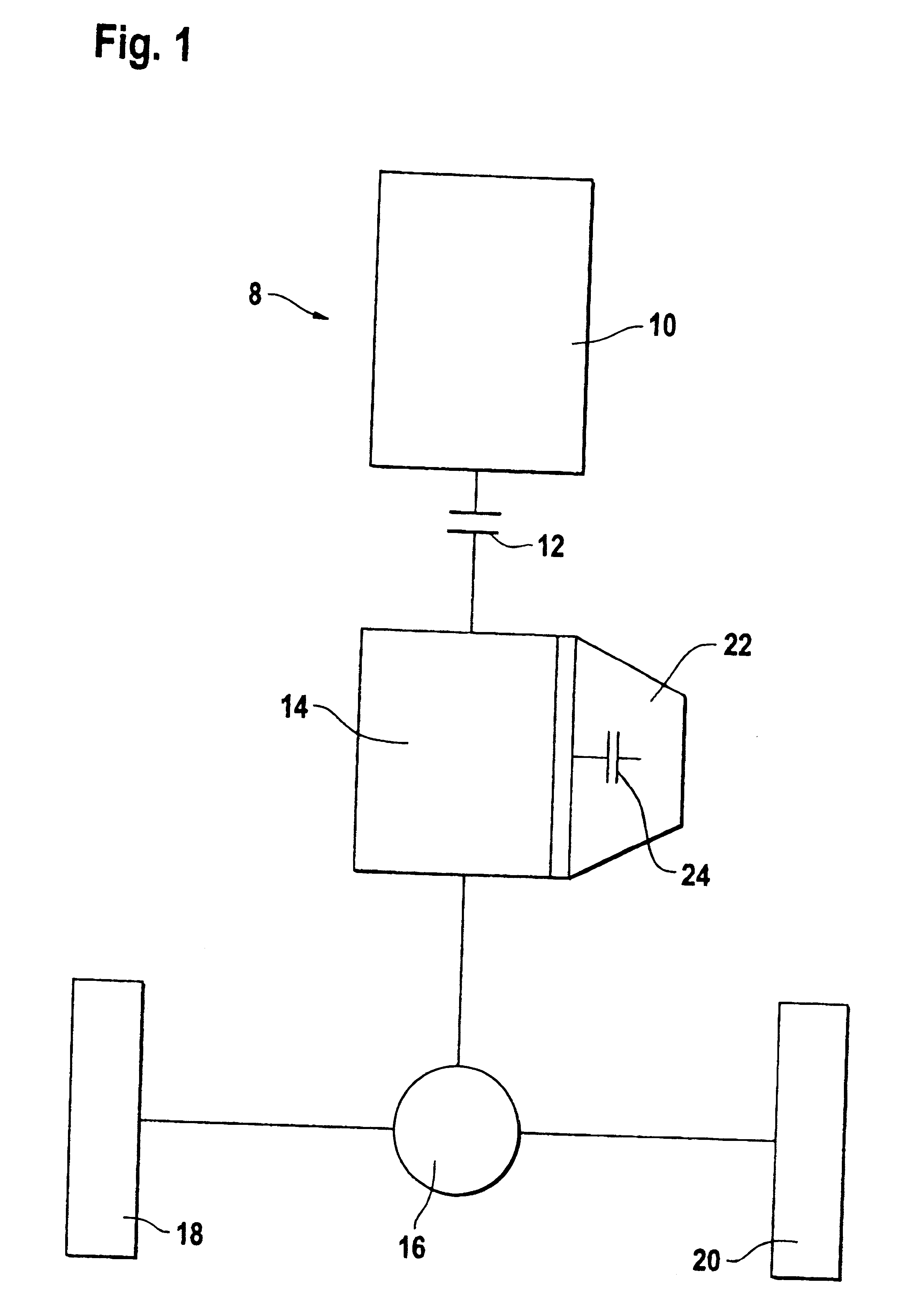
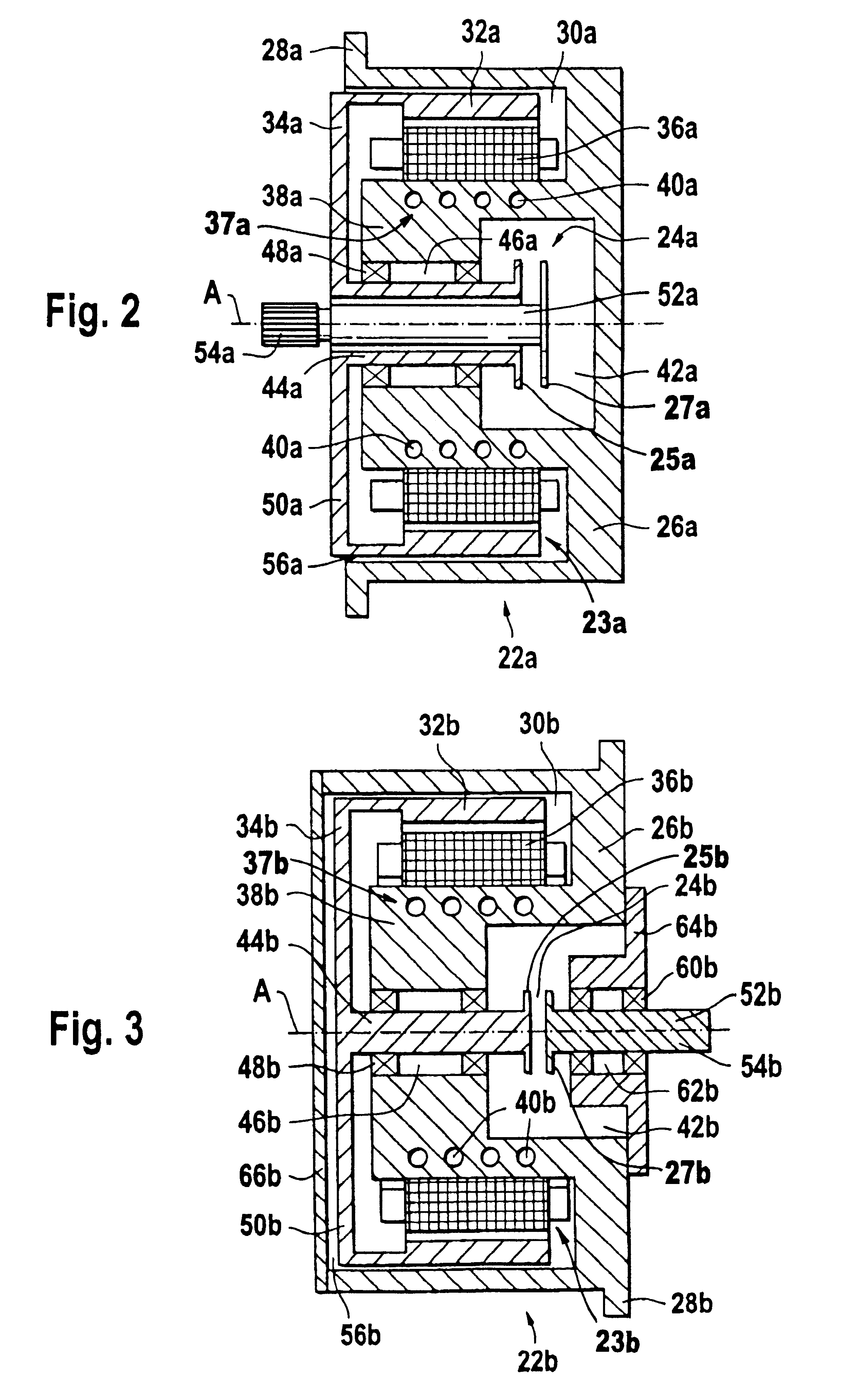
The second clutch which is integrated in the electrical machine allows the disengagement of the electrical machine from the transmission during operation of the internal combustion engine, so that the electrical machine (also referred to as the electric motor for short in the following text) does not rotate during operation of the vehicle by the internal combustion engine, thereby eliminating iron losses which would otherwise occur. According to the invention, the second clutch includes a clutch which is integrated in the electric motor rather than a clutch which is separate from the electric motor in the drive train. This may be surprising because the integration of a clutch requires a specifically designed electric motor to be produced for the parallel hybrid drive according to the invention. It is difficult to imagine this arrangement being used at all for a parallel drive in which the electric motor is at the same time intended to be used as a generator during internal combustion engine operation. In fact, it would appear to be much more advantageous to provide a separate clutch between the electric motor and the transmission so that inexpensive and available generic components are used to design the parallel hybrid drive.
However, the integration according to the invention of the second clutch in the electric motor is particularly advantageous since the
physical space for a clutch which is separate from the electric motor is saved. It has even been found that the cost outlay for providing the second clutch in the electric motor is, surprisingly, less than the cost outlay for a prior art motor with a separate clutch despite the requirement for a specifically designed electric motor or electric motor component. This is particularly true if the electrical machine, or the electric motor, is designed as a unit which is separate from the transmission, so that the unit, which has already been prefabricated, can be fitted to the transmission in a particularly cost-effective manner. When assembled, the unit can form a drive unit with the transmission and, possibly, with the internal combustion engine.
A particularly compact arrangement is possible if the electrical machine is designed as an external rotor type with a radial part which connects the cylindrical rotor to the rotor shaft. This type of design allows the rotor to radially surround the outside of the shaft bearing arrangement and for the shaft bearing arrangement to be arranged axially between the second clutch and the radial part which connects the cylindrical rotor to the rotor shaft. Furthermore, the second clutch, which is coaxial with respect to the rotor, may be arranged inside a cavity in the electrical machine, which is bounded, at least partially, by a body section of the electrical machine which is used as the
stator. The arrangement permits the rotor to radially surround the outside of at least a portion of the second clutch to save space.
In this context, is it proposed that the housing have an attachment arrangement in the vicinity of the opening, for attachment to an associated support, in particular the transmission. The attachment arrangement such, for example, as an annular attachment
flange around the opening preferably allows the opening to be at least partially closed by the correspondingly designed support. This eliminates the need for a separate closure cover or the like.
The second clutch according to the present invention may be operated mechanically, electrically, electromagnetically, hydraulically or pneumatically. In a preferred embodiment, the second clutch is a positively locking claw clutch which is preferably synchronized. For this purpose, the claw clutch may comprise a
synchronizing device having a first
pinion on the rotor shaft side, a second
pinion on the output
drive shaft side and a synchronizing
pinion which has switching claws. The axially movable synchronizing pinion is permanently engaged in a positively locking manner with a tooth
system on one of the first pinion and the second pinion and can selectively be engaged with and disengaged from a tooth
system on the other of the first and second pinions in a positively locking manner by axial movement. A synchronizing ring is preferably arranged between the first and second pinions and is designed to cause the rotation speeds of these two pinions to be matched by friction
coupling of the synchronizing pinion and other pinion, and to prevent the positively locking engagement between these two pinions from being produced before these rotation speeds are matched. It is particularly cost-effective to design the claw clutch using a synchronizing device of a motor vehicle transmission.
The invention furthermore relates to a method for disengaging the electrical machine from the drive train when the motor vehicle is in motion, so that the motor vehicle may be driven solely by the internal combustion engine without rotating the rotor. For this purpose, it is proposed that prior to disengagement, the electrical machine be actuated as an electric motor to accelerate the rotor to relieve torques acting on the torque-transmitting positively locking elements of the clutch. When the positively locking elements are relieved of torques acting on them, a
coupling element of the positively locking clutch may be operated, in the sense of disengaging it, without any major operating forces and without the risk of wear.


