
Water treatment process

a water treatment process and water technology, applied in the direction of separation processes, filtration separation, moving filter element filters, etc., can solve the problems of soda ash use, generating considerable sludge, and affecting the quality of finished water,

Inactive Publication Date: 2001-10-02
APPLIED SPECIALTIES
View PDF17 Cites 19 Cited by
  • Summary
  • Abstract
  • Description
  • Claims
  • Application Information

AI Technical Summary

Benefits of technology

This process effectively reduces hardness and anion content in water, minimizing sludge production and sodium introduction, while maintaining low operational costs and simplicity, with high efficiency in removing magnesium, calcium, and other ions.

Problems solved by technology

Hardness in water is a common problem.
(Soda ash usage unfortunately adds substantial Na.sup.+ to the finished water).
The traditional lime process generates considerable sludge, being CaCO.sub.3 and Mg(OH).sub.2, and does little if anything to reduce chloride content and has limited capability to reduce any of the other anion content (sulfate, phosphate, nitrate) of the initial water.

Method used


Image

  • Water treatment process
  • Water treatment process
  • Water treatment process

Examples


example 1

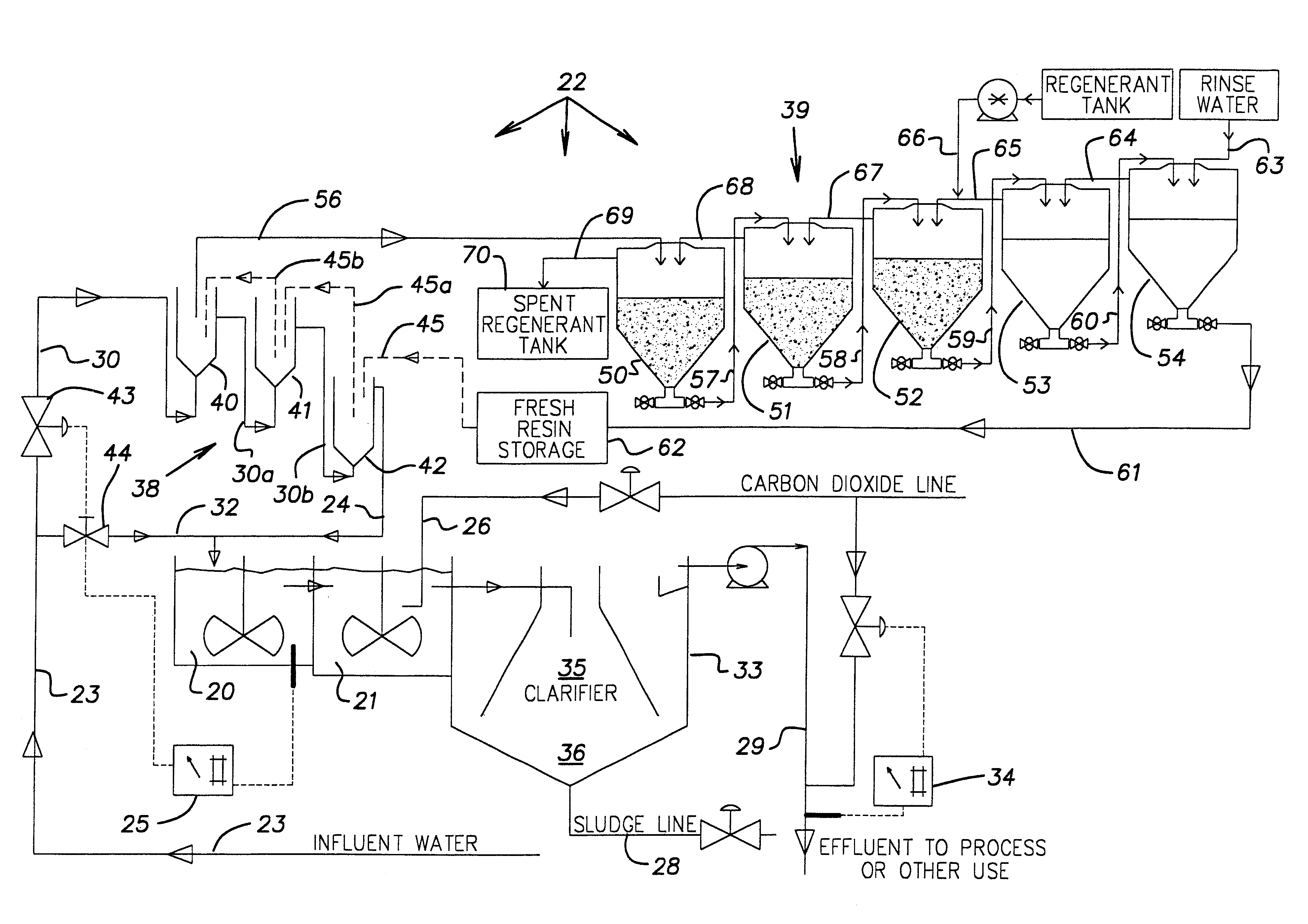
A pilot plant was set up basically as shown in FIG. 1. Tanks 40-42 were each 30-gallon conebottom tanks; tank 20 was 30 gallons (pH about 11.3-11.6) and line 32 was controlled via pH controller 25. Tank 21 (30 gallons) was used and utilized CO.sub.2 sparging via line 26 via a pH controller sensing tank 21 and maintaining pH at about 10.3-10.6. Clarifier 33 was a 70 gallon conebottom tank with overflow weir. The total flow rate was 6 gallons / min. with 2 gal / min. through line 30 to unit 38 and 4 gal / min. through line 32 directly to tank 20. Each of tanks 40-42 was filled with about one cubic foot (about 40% of capacity) of Mitsubishi DIAION SA 20A anion-exchange resin beads which had been prepared by soaking in 4% NaOH and rinsing in DI water. Total bead contact time was thus about 18 minutes.

Resin beads were moved periodically from tank 42 to tank 41 to tank 40, particularly when the pH dropped in tank 20. Tanks 50-54 were 15 gallons each; the rinse water in tank 54 came from tank 42...

example 2

Table 2 shows, for selected components, test results of water sample Nos. 6, 7 and 8 which were run through a static lab test configured or patterned basically according to the design or configuration of FIG. 2, and run as per FIG. 2 described above. The resin beads were Mitsubishi Chemical DIAION SA 20A. The numbers are parts per million.

These test results show that, to an extent that was surprising and unexpected, the process of the invention was effective in softening the water and reducing the content of selected components. The invention also surprisingly lowered the sodium and potassium concentrations, as shown in water sample No. 6.

In addition to softening the influent water, the invention also effectively reduces the concentration of undesirable anions (particularly chloride, sulfate, phosphate, nitrate and silicate) and reduces the concentration of undesirable amphoteric components and non-hardness cations. It is believed, and testing thus far has indicated, that the percen...


PUM

PropertyMeasurementUnit
flow rateaaaaaaaaaa
pHaaaaaaaaaa
flow rateaaaaaaaaaa

Abstract

An improved water softening process is provided which also reduces anion content. A first stream of water is passed through an anion-exchange unit to remove undesirable anions and raise the pH. The first stream of water is then provided to reactor / clarifier water softening equipment, where it acts as a source of hydroxyl ions. Preferably a second stream of water which did not pass through an anion-exchange unit is also provided to the water softening equipment. The streams of water are combined and processed through the softening equipment, where hardness ions are precipitated out, yielding softened water with reduced anion content. The anion-exchange system utilized preferably has a counter-current continuous resin train and a counter-current continuous resin regeneration unit.

Description

The invention relates generally to water treatment and more particularly to an improved process for softening water while reducing anion content.DESCRIPTION OF RELATED ARTHardness in water is a common problem. Hardness in water is due primarily to the presence of Ca.sup.2+ and Mg.sup.2+, and also to the presence of Ba.sup.2+ and Sr.sup.2+, all of these being hardness ions. Water is said to be "softened" when these cations are removed, such as by water softening equipment. For large-scale or large volume water softening, the traditional process is called cold lime or cold lime-soda softening. In this process the lime can be either hydrated lime (Ca(OH).sub.2) or quicklime (CaO). In large systems the lime source is stored in a storage vessel. If quicklime is used, it must first be converted to hydrated lime (Ca(OH).sub.2) by being slaked, that is, combined with water. In any event, Ca(OH).sub.2 is provided and is diluted in a lime slurry, where the Ca(OH).sub.2 dissociates into Ca.sup...

Claims


Application Information

Patent Timeline
Patent Type & Authority Patents(United States)
IPC IPC(8): B01J49/00C02F1/42C02F1/66
CPCB01J49/0086C02F1/42C02F1/66B01J49/75
Inventor SCHEUERMAN, III, CLARENCE
Owner APPLIED SPECIALTIES
Learn More